Time-Reversed Ultrasound Beats the Diffraction Limit
DOI: 10.1063/1.1537899
The hapless Humpty Dumpty often crops up as a metaphor for the second law of thermodynamics. Having fallen off his wall, Humpty really can’t be put back together again. Even if one could trace every broken bit of him back through time, it would be impossible to propel those fragments with precisely the right momentum to restore Humpty to his prelapsarian state.
But that’s not the case for whatever sound Humpty emits as he topples. To reverse sound, one doesn’t need to know the motion of every atom—just the phase, amplitude, and wavelength of the wave motion that entrains them. With the right equipment and a lossless medium, sound can be recorded, reversed, and rebroadcast to converge on the spot where it originated.
Called time-reversed acoustics, this remarkable technique has been around for about 10 years (see Mathias Fink’s article in Physics Today, March 1997, page 34 ). It began as a topic of basic research but has engendered several applications, from locating enemy submarines to zapping cancerous tumors.
Now, from one of the founders of the field, Fink, and his former graduate student Julien de Rosny, comes a new development that could extend the reach of those and other applications. The two researchers, who are based at the University of Paris VII, have demonstrated a method for focusing time-reversed waves onto spots smaller than the diffraction limit. 1
Wave equation
Reversing sound is possible in principle because the wave equation for lossless media lacks a first-order time derivative. If the forward-propagating wave field Ψ(r, t) solves the wave equation, then so too does the backward-propagating Ψ(r, −t). The aim of the time-reversing acoustician, therefore, is to create Ψ(r, −t) from Ψ(r, t).
Achieving that aim in practice takes three steps. First, one measures Ψ(r, t) with a set of transducers that act as microphones. Ideally, the transducers should completely surround the source, but, as the first experiments showed, less coverage gives acceptable results. Second, one flips the signals in time. Third, one uses the flipped signals to drive the same transducers, which, this time, act as loudspeakers.
With today’s transducer technology, ultrasound with frequencies as high as 5 MHz can be measured, flipped, and reemitted. Reversing higher-frequency waves, such as visible light, remains a challenge. But whatever type of wave one seeks to reverse, the diffraction limit gets in the way: Information on spatial scales smaller than half the wavelength doesn’t propagate and can’t be reversed by far-field transducers.
To appreciate how the diffraction limit applies in practice, consider a soprano hitting a high C. The note’s dominant wavelength is the size of the singer’s head, but around her mouth the pressure field includes evanescent terms that decay exponentially over a distance considerably shorter than the wavelength of that high C. Reversing the sound that reaches the audience would create a wave that converges on the singer’s head. But because the reversed field lacks the nonpropagating evanescent terms, it wouldn’t disappear into the singer’s mouth. Rather, when it spanned half a wavelength across, it would stop collapsing and start diverging.
Four years ago, Fink realized that he could overcome the diffraction limit for time-reversed sound. The key was to reverse not just the wave that reaches the transducers, but also the localized source term.
Wafers and sheets
To test his idea, Fink adapted a system he had developed five years ago with another of his former students, Carsten Draeger. 2 Fink and Draeger’s original system consisted of a D-shaped wafer of silicon a few centimeters across and a few millimeters thick. The waves they reversed weren’t sound waves but elastic surface waves known as Lamb waves, which travel at about a kilometer per second with a wavelength of a few millimeters. To excite the waves, Fink and Draeger used a piezoelectrically controlled vibrating needle. The same type of needle, touching the surface, could measure the waves.
Using such a system brings important advantages. A wave launched somewhere near the middle of the wafer will bounce off the wafer’s edges and reverberate through the wafer. Until the wave decays, the information it carries remains in the wafer. Moreover, thanks to the wafer’s irregular shape, the wave motion quickly becomes chaotic. That’s important because it helps to ensure that the system is ergodic—that is, the fluctuations at a particular spot represent the instantaneous fluctuations throughout the system. In time-reversal experiments, the more stirred up a system is, the fewer transducers one needs to reverse the signal. Indeed, Fink and Draeger showed that they could isotropically refocus a time-reversed wave in their wafer with just one far-field transducer.
Fink and Draeger’s transducer measures displacements throughout the wafer’s thickness. But to probe the diffraction limit, one needs to look at a small fraction of the thickness. Fink and de Rosny solved that problem in an ingenious way. Instead of a silicon wafer, they used a glass slide backed with a reflective layer of aluminum. As in the wafer experiments, a needle excites the waves, but in the newer glass slide experiments, the measuring device is a laser.
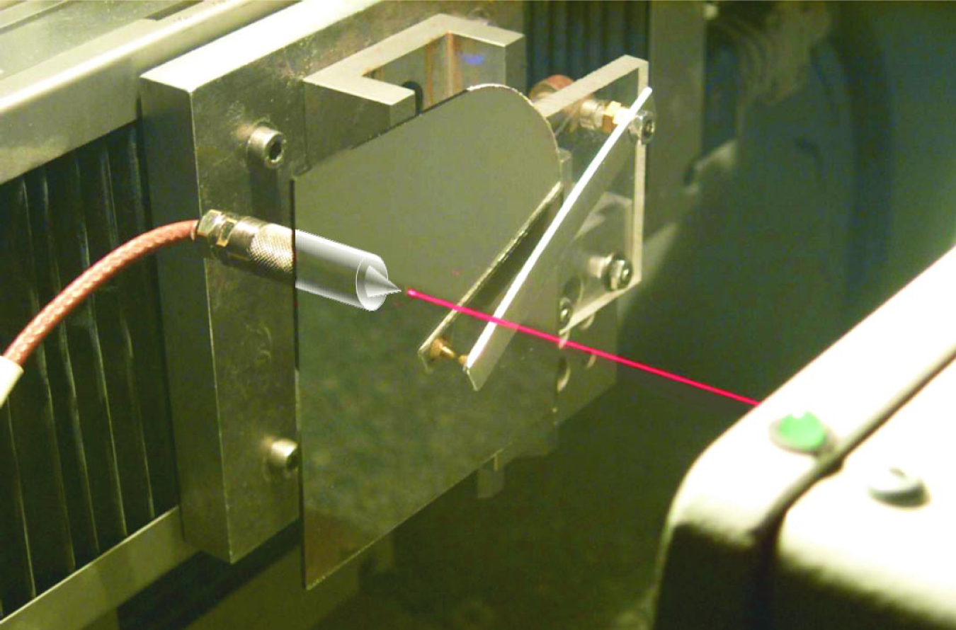
There’s another important difference between the two experiments. Fink and Draeger used two transducers: one to launch the wave and a second one, at a different spot on the wafer, to measure and launch the reversed wave. In the new experiment, Fink and de Rosny used only one transducer, located at the same spot, to launch both the forward and backward waves. Their setup appears in the photo on page 22.
Acoustic sink
Fink and de Rosny’s experiment begins when the needle, whose tip measures 100 µm (about 1/14 of the wavelength), jiggles for 5 µs to launch a pulse with a central frequency of 500 kHz. The Lamb wave spreads outward, bounces off the slide’s edges, and repeatedly washes back and forth over the now-passive needle. After 2 ms, the signal decays away.
To record the data needed for reversing the wave, Fink and de Rosny point the laser directly over the spot where the wave originates. The recording captures the localized source term, along with the propagating wave, which first returns to the source after about 250 µs. Flipping the recording creates a set of instructions that the needle follows, like a musical score, to produce a reversed wave. The laser, this time acting as a scanning interferometer, monitors the reversed wave’s progress.
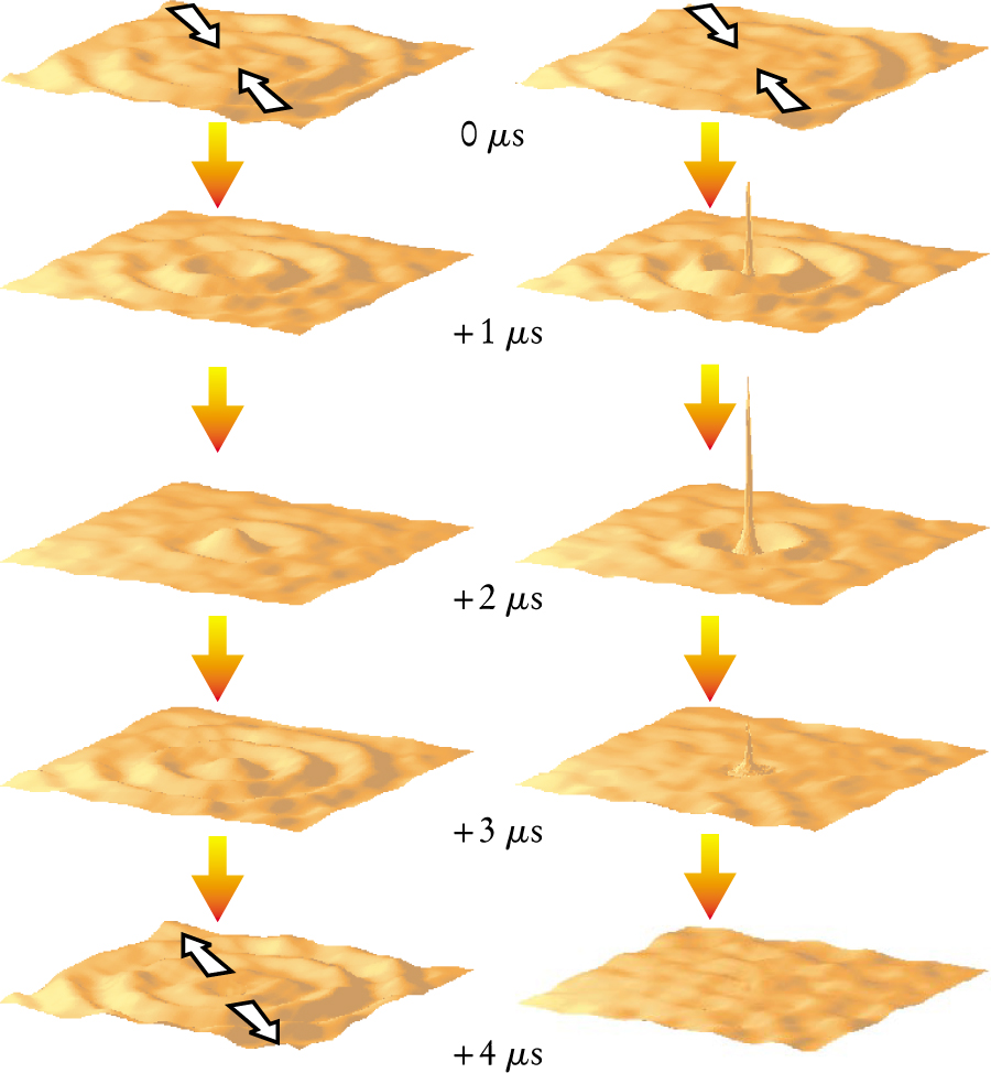
To investigate the effect of excluding or including the localized source, Fink and de Rosny run their experiment in two different modes. In the first mode, they omit the first 250 µs of the recording. Doing so ensures that only the propagating part of the wave is reversed. As shown in the accompanying figure, leaving out the localized source term produces a diffraction-limited wave that converges on the origin, then diverges.
In the second mode, Fink and de Rosny use the whole recording. As before, the reversed wave converges on the origin, but this time it pushes through the diffraction limit to focus on a spot that measures just 1/14 of a wavelength across—the same size as the tip of the exciting needle. What’s more, once the wave reaches the origin, it stops. Fink calls the phenomenon an acoustic sink.
Many potential applications of time-reversed acoustics exploit the wave’s converging properties. Focusing the energy more tightly than the diffraction limit has obvious benefits, but what’s the point if doing so requires the injection of an additional signal in situ?
One possible use might be in acoustic surgery. Imagine implanting a tiny ultrasonic sound source next to a cancerous tumor. A set of transducers surrounding the patient then picks up the source’s faint signal, which, when reversed and amplified, converges tightly on the tumor, destroying it.

In their experiment, Julien de Rosny and Mathias Fink use an aluminum-backed glass slide excited by a needle-tipped transducer and held in place with a cantilever. To record forward-propagating waves, they use a laser interferometer that they aim, as shown here, at spot directly above the exciting needle. For clarity, the beam’s reflection off the slide has been erased from the photo.
(Courtesy of Julien de Rosny, University of Paris VII.)

Omitting the localized source term causes a time-reversed wave to converge then diverge, as shown in the left-hand sequence of images. When the source term is included, as in the right-hand sequence, the wave not only stops at the origin, it also forms a peak whose width is far narrower than the half-wavelength diffraction limit.
(Adapted from ref. 1.)
References
1. J. de Rosny, M. Fink, Phys. Rev. Lett. 89, 124301 (2002).https://doi.org/10.1103/PhysRevLett.89.124301
2. C. Draeger, M. Fink, Phys. Rev. Lett. 79, 407 (1997).https://doi.org/10.1103/PhysRevLett.79.407


