Chip-scale gyroscopes get a sensitivity boost

Gyroscopes have come a long way from some of their earliest applications in nautical navigation. Tiny versions of the devices are now used to stabilize drones, measure movement in GPS-enabled equipment, and help smartphones track users’ steps throughout the day. But shrinking sizes come at a cost. Random fluctuations caused by temperature changes introduce noise that obscures the measurement of subtle rotation signals and thus limits the gyroscopes’ sensitivity. Now Hui Jing of the National University of Defense Technology and Xin Zhou of the Southern University of Science and Technology, both in China, and their colleagues have shown how small adjustments to a chip-scale gyroscope can yield a nearly 300-fold increase in its precision. 1
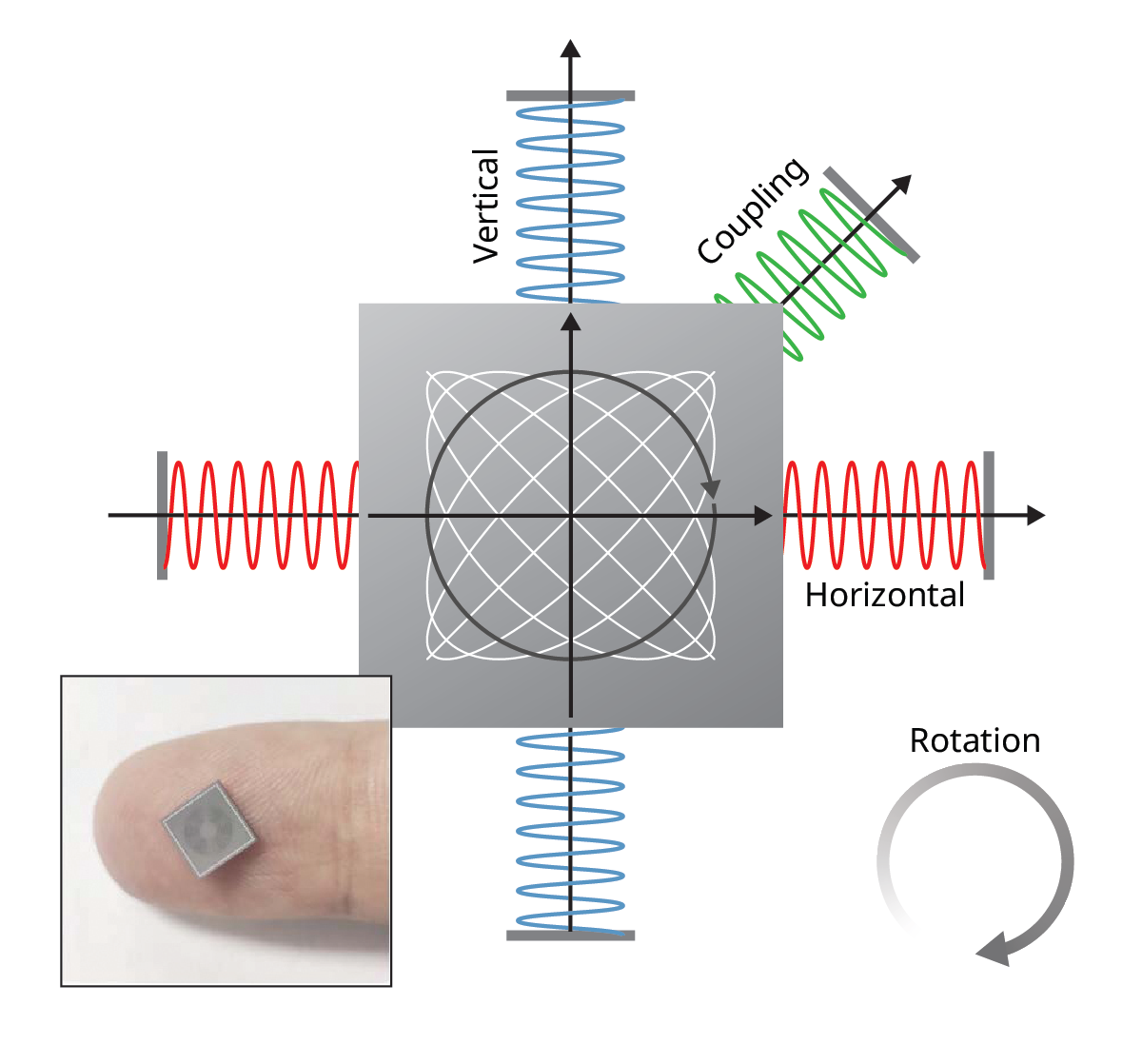
In a classical gyroscope, the displacement between a spinning disk and its surroundings can be used to measure rotation. The miniaturized versions in electronics, known as Coriolis vibratory gyroscopes, instead use vibrating materials that experience predictable and measurable forces when rotated. Both types of devices take advantage of the Coriolis effect—the deflection of a moving object subject to rotation. The standard configuration for chip-scale gyroscopes involves a disk resonator made of concentric rings connected by spokes that undergoes horizontal and vertical oscillations, represented by the red and blue springs in figure 1 . The Coriolis response in such devices is essentially linear: A small rotation yields a proportionate, small change in the oscillation frequency.
Figure 1.

A standard chip-scale Coriolis vibratory gyroscope measures rotation in a disk resonator by using two orthogonal oscillations, represented here as red and blue springs. By tuning the stiffness of the disk resonator along a third, intermediate orientation, represented by the green spring, researchers were able to increase the oscillation frequency shifts produced when the device undergoes small rotations. The chip shown in the bottom left measures 8 mm × 8 mm. (Figure adapted from ref. 1 .)
Research aimed at improving the precision of small-scale gyroscopes often focuses on noise reduction. Drawing inspiration from recent work on optical gyroscopes, Jing, Zhou, and colleagues wondered whether they could alter the device to instead amplify the response signal. They found that by tuning the stiffness of the system along a third orientation between the vertical and horizontal oscillations, represented by the green spring in figure 2 , they could alter the system response so that the effective Coriolis factor—the change of oscillation frequency relative to the angular velocity—increased by three orders of magnitude.
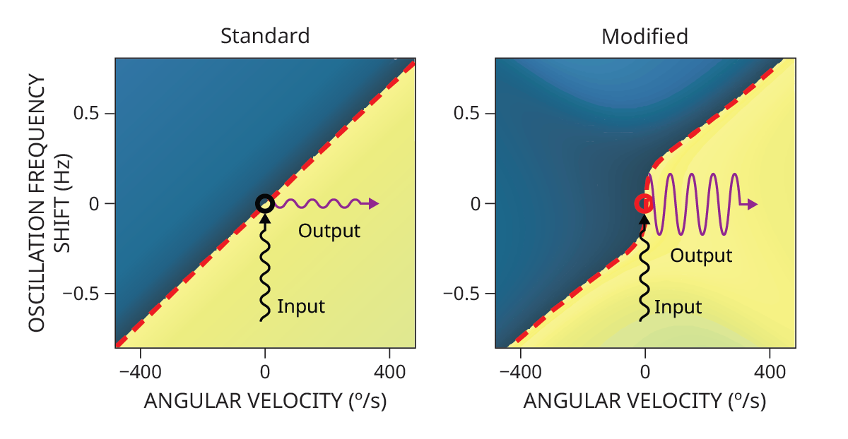
Figure 2.

For a standard Coriolis vibratory gyroscope (left), the change in the oscillation frequency is linear relative to the angular velocity that produces it. By modifying the standard design (right), researchers were able to tune the system and produce a larger frequency shift response, particularly for small angular velocities, as shown by the dashed red line. (Figure adapted from ref. 1 .)
The study serves as a proof of concept for how to build chip-scale gyroscopes with higher sensitivity, but additional work is needed for such devices to be commercially viable. To tune the frequency response of the system, the researchers needed to precisely calibrate the coupled stiffness. It will be a challenge to maintain that precision under real-world operating conditions. The nonlinear signal also complicates the translation of the signal into a measurement because it requires more complex calculations and calibration, which would need to be accounted for in a commercial design.
Many settings where gyroscopes are already used would benefit from increased sensitivity and precision, such as in vehicles and cameras for stabilization, in surgical devices for movement tracking, and in places where GPS calibration is unavailable. “The key idea,” says Zhou, “is not limited to one specific gyroscope design.” He says the principle behind the design “may be useful in other inertial sensors and possibly in other precision measurement systems where weak perturbations need to be detected.”
Reference
1. S. Zhang et al., “Cusp-singularity-enhanced Coriolis effect for sensitive chip-scale gyroscopes ,” Nature 653, 700 (2026).


