The rubidium atomic clock and basic research
DOI: 10.1063/1.2812121
You’re returning home from a conference, in a rental car on a dark, rainy road 50 miles from the airport; you’re running out of time to catch your flight, and you’re lost. As little as 10 years ago, this would have been the stuff of travel nightmares, to be shared with colleagues during a coffee break between conference sessions. Today it is less of a nightmare and more of an inconvenience. You pull your car to the side of the road, program your desired destination into the rental car’s navigation system, and let it calculate a direct route to the airport from your present location using signals from orbiting GPS (global positioning system) satellites. Thankfully, you make it home without an exciting but harrowing story to tell family and friends.
Unseen and forgotten in this now-routine use of GPS are the atomic clocks. The propagation times of signals traveling 20 000 km from space to Earth are measured at the nanosecond level, and from those measurements, positions are calculated to within, in some cases, a few centimeters. More generally, modern systems ranging from cell-phone communications to satellite navigation take advantage of atomic clocks, in particular the capabilities of small, low-power, rubidium vapor-cell clocks. How the vapor-cell clock came to play such an important role in modern timekeeping is a story that goes back half a century, and one that highlights the close interplay between basic science and technological innovation.
The vapor-cell atomic clock
The vapor-cell atomic clock is an unpretentious device. Light from a small discharge lamp passes through a vapor of rubidium atoms housed in a glass cell and is detected by a photodiode. The light intensity transmitted by the vapor is used to lock the frequency of an RF signal to an atomic transition. The RF signal can then be down-converted to generate a train of one-second pulses for timekeeping. Given its conceptual simplicity, the extent to which the vapor-cell clock’s realization relies on basic atomic and chemical physics is quite striking.
Since time intervals are defined as the elapsed phase of some stable oscillation, all clocks are, at heart, frequency standards. Just like in your wristwatch, the timekeeping signal in an atomic clock is derived from a quartz crystal oscillator. However, a crystal oscillator’s RF frequency ν xtal depends on a number of environmental factors, such as humidity, vibration, and radiation, that can cause the clock to either speed up or slow down. In the vapor-cell atomic clock, ν xtal is electronically tied to an atomic resonance, thereby transferring the stability of atomic structure to the clock’s tick rate.
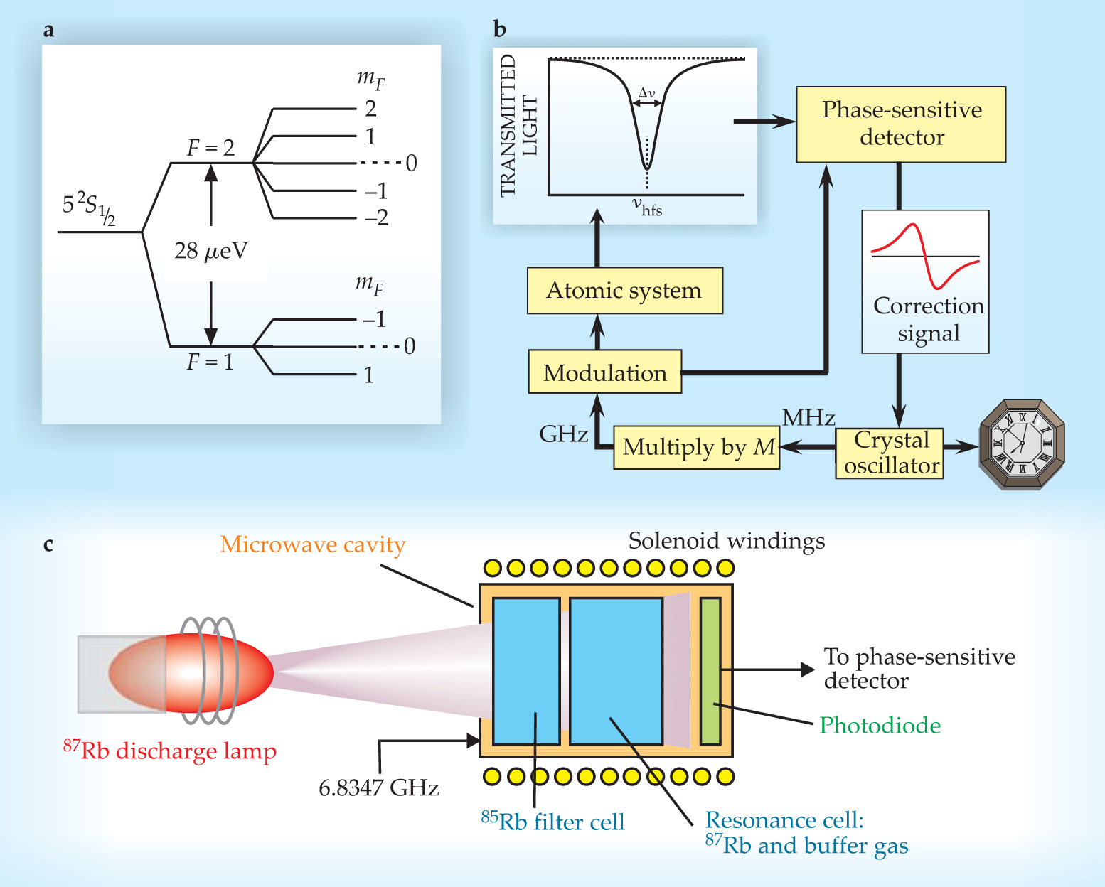
The atomic resonance that forms the basis of the Rb clock’s operation is the transition between two hyperfine states of 87Rb. As in hydrogen, the ground state of Rb is split into two hyperfine levels by the magnetic-dipole interaction between the single valence electron and the nucleus. Those states are labeled by the total-angular-momentum quantum number F, as shown in figure 1a. Each hyperfine state is further split into Zeeman sublevels, characterized by the quantum number mF. The mF = 0 sublevels are unaffected to first order by stray magnetic fields, which can arise in devices from a host of internal and environmental sources. The so-called 0–0 transition between the F = 2, mF = 0 and F = 1, mF = 0 states, with frequency ν hfs = 6.8347 GHz, is unaffected by such fields and is ideal for stabilizing ν xtal.

Figure 1. A generic rubidium vapor-cell atomic clock. (a) The ground state of 87Rb is split into two hyperfine levels, characterized by the quantum number F. The transition between the two mF = 0 sublevels, unchanged to first order by stray magnetic fields, is used to stabilize a crystal oscillator’s frequency. (b) The frequency of a voltage-controlled crystal oscillator, scaled up by a factor M, is locked to the hyperfine-splitting frequency ν hfs = 6.8347 GHz using phase-sensitive detection. The control voltage corrects the crystal oscillator’s frequency. (c) The clock’s atomic system consists of a few simple elements.
Figure
As illustrated in figure
Optical pumping and the light shift
Without a population imbalance between the 87Rb hyperfine states, there can be no net absorption of microwaves by the atoms in the resonance cell: The rate of photons leaving the field through absorption would be counterbalanced by the rate of stimulated emission repopulating the field. For 87Rb, the hyperfine-energy-level separation is only 28 μeV, whereas gas-phase kinetic energies are approximately 40 meV. Thus, under normal conditions, the vapor-phase atoms populate both hyperfine manifolds equally. The system for creating the necessary population imbalance is a direct outgrowth of the Nobel Prize–winning work of Alfred Kastler, who showed that light can create a nonthermal population distribution among atomic energy levels in a process known as optical pumping. 1
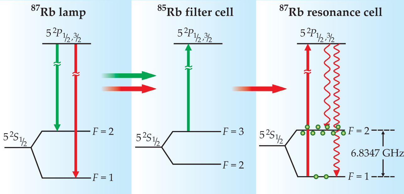
As illustrated in figure 2, a 87Rb discharge lamp emits light at frequencies that connect Rb’s excited states with each ground-state hyperfine level. Due to a coincidence of nature, spectral lines associated with 87Rb’s F = 2 state are nearly degenerate with those of 85Rb’s F = 3 state. Thus, as Peter Bender and colleagues explained in a 1958 Physical Review Letter, 2 a filter of 85Rb vapor can remove the F = 2 spectral component from a 87Rb lamp’s emission. When the filtered lamplight reaches the 87Rb atoms in the resonance cell, it preferentially excites atoms out of the F = 1 state. Decay from the excited state repopulates both hyperfine levels, but those atoms returning to the F = 1 state are excited again, so that after several absorption–decay cycles a nonthermal population distribution is created. The easy filtering of lamplight is the primary reason present-day vapor-cell clocks use Rb instead of other alkali metals.

Figure 2. The rubidium-87 lamp emits light at frequencies associated with both hyperfine states: There are two fluorescence lines from the 52 P 1/2 state of wavelength 795 nm and two fluorescence lines from the 52 P 3/2 state of wavelength 780 nm. Each pair of lines is separated by approximately 0.014 nm. Due to a coincidence of nature, the spectral lines associated with 87Rb’s F = 2 state are absorbed by 85Rb atoms; the other lamp lines are unaffected. When the filtered lamplight passes into the resonance cell, several cycles of optical absorption and emission create a population imbalance between the F = 2 and F = 1 states.
The discharge lamp not only drives the optical-pumping process but also provides a signal that indicates when the microwave field is on resonance with the 0–0 transition. When the field is off resonance, there are few atoms in the F = 1 state, so most of the lamplight passes through the resonance cell unabsorbed. But when the microwave frequency equals ν hfs, the atoms return to the F = 1 state, and the intensity of transmitted lamplight measured by the photodiode decreases.
Unfortunately, the lamplight in the resonance cell perturbs Rb’s energy-level structure. Due to the so-called light shift, discussed in
The role of the buffer gas
The key to generating a correction signal for the crystal oscillator is to get the 87Rb atoms in the resonance cell to absorb microwave radiation in a narrow frequency band around ν hfs. Since the efficacy of the correction signal is measured by the instability of the crystal oscillator’s frequency, given by (Δν/ν hfs)/(S/N), an atomic transition with a high signal-to-noise ratio S/N and a narrow linewidth Δν results in the best performance (see the article by James Bergquist, Steven Jefferts, and David Wineland, Physics Today, March 2001, page 37 ).
The resonance cell of a Rb clock contains not only 87Rb vapor at a pressure of 10−2 Pa but also a buffer-gas mixture of nitrogen and a noble gas, with a total pressure of about 103 Pa. The buffer gas plays several roles, two of which are directly related to the transition linewidth.
In 1953 Robert Dicke wrote a two-page paper in Physical Review that set the stage for vapor-cell clock development.
6
As described in
In modern vapor-cell clocks, however, the buffer-gas pressure is thousands of times larger than what is needed for Dicke narrowing. One reason for the higher pressure is to protect the Rb atoms from collisions with the bare glass walls of the resonance cell. Narrow atomic resonances require not only the elimination of Doppler broadening, but also a long coherence time T 2, where Δν ~ 1/T 2. When a 87Rb atom absorbs microwaves, its wavefunction becomes a superposition of the F = 1 and F = 2 states, and for narrow resonances, the superposition state’s phase must remain constant for long periods of time. Unfortunately, when an atom collides with a bare glass wall, the superposition state’s phase is randomized, so T 2 is limited by the atom’s flight time across the resonance cell. A collision with a molecule of N2 or noble gas, however, only weakly affects the superposition state’s phase. Consequently, the high-pressure buffer gas can slow the diffusion of Rb atoms to the glass walls without appreciably affecting the superposition state’s phase, and thereby lengthen T 2.
To say that a buffer-gas atom or molecule only weakly affects the superposition state’s phase camouflages a great deal of complicated physics, and interest in the effects of buffer-gas collisions on the 0–0 transition’s linewidth motivated considerable research in the 1960s and 1970s. Today it continues to influence basic research as the need for better clocks motivates a deeper understanding of the interaction between buffer-gas species and alkali-metal atoms. As an example, William Happer and his colleagues have recently studied binary collisions between Rb and noble-gas atoms 7 and have discovered that collisional changes in electron density at the alkali nucleus can be important in limiting T 2.
The other reason for relatively high buffer-gas pressure has to do with the efficiency of optical pumping. An isolated Rb atom, after excitation by the lamplight, returns to the ground state by emitting a fluorescent photon. Alkali metals, however, are notorious for reabsorbing their fluorescent photons in a process known as radiation trapping, which has the effect of undoing the optical-pumping effect of the lamp-light. 8 It’s as if there were an extra source of light in the resonance cell that could excite atoms out of the 87Rb F = 2 hyperfine level. But radiation trapping can be avoided with the addition of N2 as a buffer gas. When a Rb atom collides with a molecule of N2, Rb electronic energy is converted into N2 vibrational energy, and the Rb atom returns to its ground state without fluorescing. In a very real sense, efficient optical pumping in the vapor-cell clock relies on the chemical physics of intermolecular energy transfer.
The light shift
The light shift is one of the earliest known manifestations of what is today generally known as the AC Stark shift, and it can be understood as a consequence of energy conservation. 16 Consider a three-level atom interacting with an optical field of frequency ω that drives the |2〉 → |3〉 transition. Suppose that in the absence of the field–atom interaction there are N photons in the field, so that the total energy of the field–atom system is E 2 + Nℏω. With the interaction turned on and the field off resonance, the atom spends a fraction f of its time in state |3〉, and states |2〉 and |3〉 are shifted in opposite directions by an amount δν LS. Conservation of energy then requires that
from which it follows that δν LS = f(ω 0 – ω)/(1 − 2f).
The parameter f can be determined from a rate-equation model of the interaction process involving the Einstein A and B coefficients: f = Bρg(ω)/[A + 2Bρg(ω)], where ρ is the energy density of the field and g(ω) corresponds to the optical transition’s lineshape. Without going into the details, it can be shown that
where I is the intensity of the optical field and Γ is the optical transition linewidth. The shift in the energy of |2〉 causes a change in the |1〉 ↔ |2〉 energy-level spacing, which is detected as a light-induced change in ν hfs.
The AC Stark shift is fundamentally related to the Lamb shift, which arises from an atom’s interaction with the vacuum. The light shift arises from real photons driving virtual transitions in an atom (that is, ω ≠ ω 0); the Lamb shift arises from virtual photons driving virtual transitions in an atom. The relationship was not lost on the original investigators, and in a play on words Alfred Kastler suggested renaming the phenomenon the Lamp shift. 17 In fact, in cavity quantum electrodynamics experiments it may be difficult to disentangle the two phenomena. 18

Dicke narrowing
Consider the one-dimensional problem of a radiating atom of mass m confined to a square well of infinite depth and width L. In a quantized theory of radiation, the Doppler effect is a consequence of momentum conservation between the radiating atom and the emitted photon observed in the laboratory frame. Energy conservation between the initial and final states gives
where E e and E g are the excited-state and ground-state energies, v i and v f are the initial and final velocities, and λ emit is the wavelength of the emitted photon. Momentum conservation gives
where the ± sign refers to the emitted photon’s direction relative to v i. Combining equations 1 and 2 gives the textbook nonrelativistic expression for the Doppler shift of the emitted photon in terms of the rest-frame transition wavelength λ 0 = hc/(E e – E g):
Because the atom is confined to a square well, however, its momentum is quantized and can only change in units of h/2L. If the photon’s momentum is smaller than that (that is, λ emit/2L > 1), then the atom’s momentum state cannot change following photon emission. In such cases the field–atom interaction must be viewed in the broader context of energy and momentum conservation for the atom–potential-well system. The emitted photon’s momentum is then transferred to the potential well, which presumably has infinite mass, so that the atom’s velocity remains unchanged and the Doppler shift is zero.

State of the art
The best Rb clocks ever built are now flying on GPS satellites. Those clocks are so stable that in three hours they accrue less than half a nanosecond of time error. In the same three hours, general relativistic effects due to the satellite’s elevated location, if left uncorrected, would cause a satellite clock and a terrestrial clock to accrue a little more than 5 microseconds of time offset. In other words, GPS Rb atomic clocks can sense those general relativistic effects at the fourth significant figure. (See the article by Neil Ashby, Physics Today, May 2002, page 41 .)
Rubidium clocks aboard satellites operate under different conditions than do terrestrial clocks, and the need to adapt the clocks to those conditions has led to a range of physical and chemical research. For example, the inner glass surface of a discharge lamp experiences a harsh environment, with energetic ions etching the surface and alkali-metal atoms chemically interacting with the exposed glass. If that chemistry were to lead to lamp failure in a terrestrial clock, one would simply ship the device back to the manufacturer for a replacement lamp. However, no one services a failed clock on a GPS satellite, so the lamps must operate unattended and reliably throughout the satellite’s many-year mission. In the 1980s the question of a lamp’s lifetime motivated Robert Frueholz and his colleagues at The Aerospace Corporation to study alkali–glass physical chemistry. 9 Frueholz and colleagues used electron spectroscopy and secondary-ion mass spectrometry to show that Rb forms an oxide on the lamp’s inner glass surface and penetrates into the glass matrix, quite likely taking the form of a rubidium silicate. The complete depletion of Rb through those mechanisms would lead to a lamp’s failure. Using differential scanning calorimetry, the researchers then determined the rates at which various glass types consume Rb. As a result of their work, clock manufacturers can now determine how much liquid Rb needs to be deposited into a lamp to guarantee its operation over any specified mission lifetime.
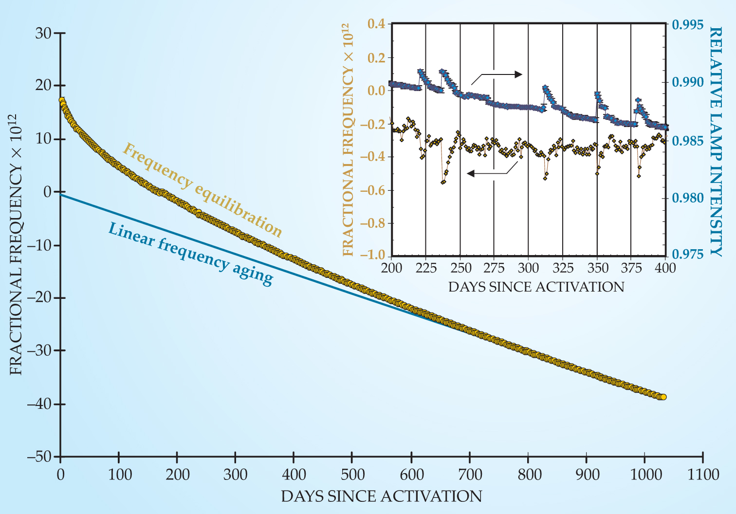
An important area of current research concerns the slow changes in a clock’s frequency over time. Figure 3 shows the frequency variations of a GPS satellite clock after it was turned on; its general characteristics are common to all rubidium clocks. Following activation the clock experienced a very slow exponential equilibration until it settled down to a linear frequency change with time. The mechanisms that drive those two processes are not yet understood. 10 The figure’s inset shows an expanded view around days 200 to 400, illustrating several slight frequency jumps that are correlated with small changes in the lamp’s output. There, the influence of the light-shift effect is evident—the intensity of lamplight in the resonance cell directly affects the clock frequency—but the cause of those small lamp changes is not yet known. Though not shown in the figure, the frequency of every Rb clock undergoes slight stochastic fluctuations. In the long term, those fluctuations correspond to Brownian-type motion, and again the physical process that drives them is not understood. Clearly, although the Rb clock has been studied for 50 years, much remains to be understood and improved.

Figure 3. Reconstructed frequency history of a rubidium atomic clock aboard a GPS satellite. Two phenomena contribute to the long-term frequency variations: slow exponential frequency equilibration, with a time constant of 235 days, and linear frequency aging at a rate of 3.7 × 10⁻¹⁴/day. It is not known whether the phenomena are driven by the same physical mechanism. The inset shows clock frequency jumps arising from the light shift (see
The laser-pumped vapor-cell clock
It likely seems old-fashioned to use discharge lamps when semiconductor lasers are so readily available. Shouldn’t it be a simple matter to replace the lamp and filter cell with a diode laser and significantly increase the efficiency of optical pumping and hence the clock signal? That was the thinking of researchers in the mid-1980s, who anticipated that the use of diode lasers would lead to great improvements in clock stability and better control of the light shift. Unfortunately, that happy situation was not so easily realized: Optical pumping with diode lasers did produce a 10-fold increase in clock-signal amplitude, but it also produced a 100-fold increase in the noise. Thus, with an overall reduction in signal-to-noise ratio, the first diode-laser-pumped vapor-cell clocks had poorer frequency stability.
That puzzling situation motivated research into what may best be called the stochastic field–atom interaction problem. No real-world electromagnetic field corresponds to the textbook monochromatic field, and random fluctuations in a field’s phase and intensity can alter the nature of the field–atom interaction in qualitative and quantitative ways. In the case of the laser-pumped clock, researchers discovered that the basic light–matter interaction converts a field’s phase noise into absorption cross-section fluctuations, which, in turn, produce noise in the transmitted laser intensity. 11 That problem was particularly severe with the cleaved-facet diode lasers used in the early studies, since, as bad luck would have it, their noise characteristics were optimal for converting phase noise into intensity noise.
Once the noise-enhancement process was understood, efforts turned toward mitigation strategies, which have largely proved effective: Either one can use diode lasers with narrow linewidths, which have low phase noise, or one can increase the buffer-gas pressure in the resonance cell to 104 Pa to make the atoms less sensitive to the field’s phase fluctuations. At high buffer-gas pressures, the frequent 87Rb–buffer collisions interrupt the alkali atoms as they attempt to follow the laser’s fluctuating phase, so that the Rb vapor responds to the average laser phase instead of its instantaneous variations.
Although research into the stochastic field–atom interaction and its implications for clock performance continues, 12 investigators’ attention has also turned to the light shift. Not only does the multilevel nature of real atoms complicate the light shift, but in a laser-pumped clock the laser frequency is typically modulated in order to actively lock the laser to the atom’s absorption. That leads to a modulation of ν hfs, which can affect the clock’s stability. Understanding and controlling the light shift, and mitigating its deleterious effects on laser-pumped clock performance, is an active area of research.
Interfering pathways of excitation
Consider a three-level atom interacting with a bimodal electric field
Shortly after the field is turned on,
where rmn = 〈m|r|n〉, the first e is the electron charge, the second e is the natural logarithm base, and φ is the phase difference between the two components of the field. The probability P 3 of finding the atom in state |3〉 is simply |c 3|2, and can be found by integrating equation
In the case where r 32 = r 31 e iθ , so that those two matrix elements differ only in phase, equation
If the phase of the field’s b mode varies rapidly and randomly with respect to the a mode, then the cosine term of equation

The chip-scale atomic clock
The coherent-population-trapping atomic clock is a radical departure from the traditional vapor-cell clock, and whether that will prove to be advantageous is an open question of great interest. With the CPT clock, the signal is generated in an all-optical fashion:
13
The laser field is modulated at a frequency near ν hfs/2, derived from a harmonic of ν xtal, to produce sidebands in the laser spectrum above and below the unperturbed laser frequency. When the separation between the sidebands equals ν hfs, both hyperfine levels are simultaneously coupled to the same excited state. The two excitation pathways then interfere destructively (see

Figure 4. The proverbial black box (left) is a commercial lamp-pumped rubidium clock. On the right is the physics package of a coherent-population-trapping chip-scale atomic clock developed at NIST, which contains the laser, optics, resonance cell with alkali vapor and buffer gas, and photodetector.
(Chip-scale clock image from ref. 14.)

Independent of size, there is another, less tangible motivation for CPT clock research. As discussed in connection with figure 3, researchers have much to learn about vapor-cell clock physics. Perhaps having two qualitatively different manifestations of a vapor-cell clock will provide a point of comparison that can illuminate the origins of frequency equilibration, frequency aging, and random-walk frequency noise. That such a comparison will prove fruitful is, unfortunately, not guaranteed. The only certain conclusion is that the technological drive to develop vapor-cell clocks for diverse applications will continue to motivate atomic and chemical physics research well into the 21st century. And without that close connection between basic research and technological innovation, it would be much harder to find your way to the airport on a dark rainy night when you’re lost.
I thank The Aerospace Corporation for support under the Mission-Oriented Investigation and Experimentation program, funded by US Air Force Space and Missile Systems Center under contract FA8802-04-C-0001.
References
1. A. Bloom, Sci. Am. 203, 72 (1960); https://doi.org/10.1038/scientificamerican1060-72
W. Happer, W. van Wijngaarden, Hyperfine Interact. 38, 435 (1987). https://doi.org/10.1007/BF023948552. P. Bender, E. Beaty, A. Chi, Phys. Rev. Lett. 1, 311 (1958). https://doi.org/10.1103/PhysRevLett.1.311
3. W. Happer, Light Propagation and Light Shifts in Optical Pumping Experiments, Pergamon, New York (1970), p. 51.
4. J. Camparo, R. Mackay, J. Appl. Phys. 101, 053303 (2007). https://doi.org/10.1063/1.2435914
5. J. Camparo, R. Frueholz, C. Volk, Phys. Rev. A 27, 1914 (1983). https://doi.org/10.1103/PhysRevA.27.1914
6. R. Dicke, Phys. Rev. 89, 472 (1953). https://doi.org/10.1103/PhysRev.89.472
7. D. K. Walter, W. M. Griffith, W. Happer, Phys. Rev. Lett. 88, 093004 (2002); https://doi.org/10.1103/PhysRevLett.88.093004
P. Oreto et al., Phys. Rev. A 69, 042716 (2004). https://doi.org/10.1103/PhysRevA.69.0427168. J. C. Camparo, S. B. Delcamp, Opt. Commun. 120, 257 (1995). https://doi.org/10.1016/0030-4018(95)00426-9
9. R. Frueholz, M. Wun-Fogle, J. Am. Ceram. Soc. 66, 605 (1983); https://doi.org/10.1111/j.1151-2916.1983.tb10606.x
R. Cook, R. Frueholz, Proceedings of the 42nd Annual Frequency Control Symposium, IEEE, Piscataway, NJ (1988), p. 525. https://doi.org/10.1109/FREQ.1988.2765110. J. Camparo, C. Klimcak, S. Herbulock, IEEE Trans. Instrum. Meas. 54, 1873 (2005); https://doi.org/10.1109/TIM.2005.853217
J. Coffer, B. Sickmiller, J. Camparo, IEEE Trans. Ultrason. Ferroelectr. Freq. Control 51, 139 (2004); https://doi.org/10.1109/TUFFC.2004.1320761
J. Camparo, IEEE Ultrason. Ferroelectr. Freq. Control 52, 1075 (2005). https://doi.org/10.1109/TUFFC.2005.150399311. J. Camparo, J. Coffer, Phys. Rev. A 59, 728 (1999); https://doi.org/10.1103/PhysRevA.59.728
J. Coffer, M. Anderson, J. Camparo, Phys. Rev. A 65, 033807 (2002). https://doi.org/10.1103/PhysRevA.65.03380712. J. J. Townsend, J. G. Coffer, J. C. Camparo, Phys. Rev. A 72, 033807 (2005); https://doi.org/10.1103/PhysRevA.72.033807
M. Huang, J. G. Coffer, J. C. Camparo, Opt. Commun. 265, 187 (2006). https://doi.org/10.1016/j.optcom.2006.03.00413. J. Vanier, Appl. Phys. B 81, 421 (2005). https://doi.org/10.1007/s00340-005-1905-3
14. S. Knappe et al., Appl. Phys. Lett. 85, 1460 (2004). https://doi.org/10.1063/1.1787942
15. J. Vanier, C. Audoin, The Quantum Physics of Atomic Frequency Standards, Adam Hilger/IOP, Bristol, UK (1989), chap. 3. https://doi.org/10.1887/085274434X
16. J. Bjorkholm, P. Liao, Lecture Notes in Physics: Volume 43, Springer, Berlin (1975), p. 176. https://doi.org/10.1007/3-540-07411-2_272
17. A. Kastler, J. Opt. Soc. Am. 53, 902 (1963). https://doi.org/10.1364/JOSA.53.000902
18. J. Camparo, P. Lambropoulos, J. Opt. Soc. Am. B 19, 1169 (2002). https://doi.org/10.1364/JOSAB.19.001169
More about the authors
James Camparo is a senior scientist at The Aerospace Corporation in Los Angeles.
James Camparo, Aerospace Corporation, Los Angeles, US .


