Laser-driven plasma-wave electron accelerators
DOI: 10.1063/1.3099645
In conventional accelerators, energy from RF electromagnetic waves in vacuum is transformed into kinetic energy of particles driven by the electric field. In high-energy-physics colliders, some of that kinetic energy is in turn transformed into short-lived exotic particles. The new crown jewel of colliders is the recently completed Large Hadron Collider at CERN (see the Quick Study by Fabiola Gianotti and Chris Quigg in Physics Today, September 2007, page 90 ). The LHC, a 27-km-circumference ring for accelerating and storing countercirculating beams of 7-TeV protons, has a stored beam energy exceeding 300 MJ. The collider’s design luminosity (collision rate per unit scattering cross section) of 1034 s-1 cm-2 is two orders of magnitude greater than that of its immediate predecessor, the Tevatron collider at Fermilab.
Accelerator-based light sources rely on the fact that when beams of GeV electrons interact with magnetic fields or materials, they emit radiation at frequencies ranging from microwaves to gamma rays. A new generation of free-electron lasers (FELs) powered by e− beams from linear accelerators will soon be delivering x-ray beams of unprecedented peak brightness, orders of magnitude greater than one gets from conventional synchrotron light sources. The Linac Coherent Light Source (LCLS) at SLAC, for example, is powered by a high-quality beam of 14-GeV electrons from a kilometer-long segment of the laboratory’s venerable two-mile linear accelerator. Passing finally through a 100-m-long undulator—a periodic sequence of bending magnets—the e− beam generates subpicosecond bursts of coherent 8-keV x rays (see Physics Today, May 2005, page 26 ).
The technology and physics of the accelerators that power today’s light sources and colliders have been developed and improved over many decades. As the LHC and LCLS become operational, they will equip scientists with powerful new capabilities for answering key questions. Those machines will also point to what is needed next. One thing is certain: Scientists will want higher energy, luminosity, and brightness. Which brings us to the central issue of size and cost: At some point, society will decide that bigger accelerators built with today’s technology are simply unaffordable. To survive, we must develop new technologies to make accelerators more compact and more economical.
The quest for smaller and cheaper
Thirty years ago Toshiki Tajima and John Dawson at UCLA proposed a new way to accelerate electrons. 1 They argued that one could use a plasma medium—for example, ionized hydrogen or helium—to transform electromagnetic energy from a laser pulse into the kinetic energy of accelerated electrons by letting laser pulses excite large-amplitude plasma density waves. 2 (See the article by Chandrashekhar Joshi and Thomas Katsouleas in Physics Today, June 2003, page 47 .) In that scheme, called laser–plasma acceleration, radiation pressure from an intense laser pulse fired into the plasma causes the electrons to move out of its path. Because the much heavier ions barely move, they are left unshielded. Some distance behind the laser pulse, the electrostatic force exerted by the ions on the electrons pulls them back, creating an electron density peak. The resulting pattern of alternating positive and negative charges, called a plasma wave or laser wake, supports a strong longitudinal electric field (see figure 1).

Figure 1. Laser plasma acceleration. An intense laser pulse traversing a plasma excites a plasma wave in its wake. The wave accelerates electrons injected from an external source or trapped from the plasma. Confined in a narrow channel, the plasma guides the propagating laser pulse and prevents its diffraction.
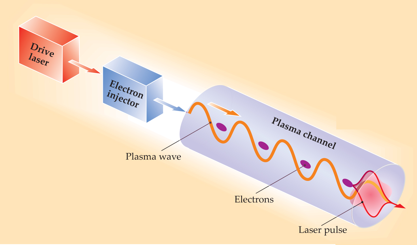
The wave oscillates at the plasma frequency, which scales as the square root of n e, the plasma’s density of free electrons, and has a wavelength typically 10–100 µm. That’s several orders of magnitude shorter than the typical RF wavelength of conventional accelerators. The amplitude of the plasma wave—that is, the electric field strength—is proportional to the laser intensity (for intensities less than 1018 W/cm2) times
The ability of plasmas to support very large electric fields was demonstrated in the 1980s by Joshi’s group at UCLA. 3 Not until 2004, however, did three independent groups demonstrate that under the right conditions, LPAs can produce e− beams with a narrow spread of final energies. 4–6 The narrow energy spread is usually essential for a useful e− beam. The highest energy of such high-quality e− beams achieved to date with an LPA is about 1 GeV, accelerated by our group at Lawrence Berkeley National Laboratory (LBNL) in a plasma structure only 3 cm long. 7
Where do the electrons come from in the first place? In nearly all experiments to date, the accelerated electrons start out as free “background” electrons in the plasma that get trapped in the large-amplitude plasma wake. Consider an ocean-wave analogy. Ordinarily on the open sea, the undulating motion doesn’t transport water in the direction of the wave’s propagation. But when it approaches a beach and breaks, the wave sprays water and trapped debris forward. Similarly, a plasma wake can break and produce trapped and accelerated electrons. It’s like a tsunami near shore grabbing and propelling anything in its path—but without much real control. So techniques now under development to control the trapping, as well as beam-injection alternatives to trapping, are key to the eventual applicability of plasma acceleration.
An interesting alternative to LPAs is the use of intense bunches of electrons instead to excite the requisite high-amplitude plasma waves. Significant progress has been made experimentally over the past decade on those so-called plasma wakefield accelerators. Recently, using the powerful 42-GeV electron beam at SLAC as a driver and a 1-m-long plasma column, PWFA experimenters observed acceleration of electrons in the tail of the drive bunch to 85 GeV. 8 That is, a small fraction of the electrons at the back of the bunch were riding the wake it generated at just the right phase to get accelerated. Although most electrons in the bunch were decelerated, the experiment showed that plasmas can sustain coherent wakefields over meter-scale distances. If such extended accelerating fields, driven either by laser light or particles, were to act on a well-defined electron bunch for a distance of 10 m, it could produce a beam of hundreds of GeV.
In this article we concentrate on LPAs. An overview of progress on PWFAs can be found in . Although LPAs have not yet reached the tens of GeV obtained by PWFAs, they have produced well-defined beams with energy spreads of only a few percent, and they have done it with lasers of moderate size and cost. The early experiments used bulky carbon dioxide lasers, but today’s experiments are done with titanium:sapphire laser systems with peak powers reaching hundreds of terawatts delivered in pulses lasting a few tens of femtoseconds. The possibility of compact multi-GeV linear accelerators, located at universities, national laboratories, and even hospitals for a wide variety of applications in basic science and medicine, has triggered worldwide interest, with many new groups emerging to advance the field.
The basic approach for building an LPA follows the paradigm of a conventional accelerator. A conventional linac consists of a power source—for example, an array of klystron tubes; an RF accelerating structure that confines and shapes the RF power to generate the requisite longitudinal electric fields; and an injector that puts electrons into the RF fields at just the right moment. Similarly, we envision that a tunable, controllable LPA would have a laser as its power source, a plasma as its accelerating structure, and a means of injecting or trapping electrons. The excitation of the accelerating fields and the production of the initial e− beam are separate issues, and they can be tuned independently.
Physics of a laser–plasma accelerator
For charged particles to reach high energies, electric fields must act on them over extended distances. Furthermore, to obtain high-quality beams with little spread in energy or trajectory, one must choose the accelerator parameters carefully. Three key design issues for a successful LPA are the so-called three Ds of the trade: diffraction, dephasing, and depletion.
The diffraction problem stems from the fact that when a laser pulse is focused, there is only a finite distance over which the beam radius r is small enough to yield the requisite high intensity. That distance, called the Rayleigh length, is proportional to r 2 at the focus. Three methods can be enlisted to overcome diffraction. The first is to guide the laser pulse by exploiting an effect called relativistic self-focusing, which occurs when the laser power exceeds a critical power and when the pulse duration is long compared with the plasma-wave period. The critical power is proportional to 1/n e, which would favor operating at high density. But in the high-n e regime, the laser pulse propagating through the plasma is inherently unstable, typically producing e− beams with unacceptably large energy spreads.
Alternatively, one could get a long interaction distance by using a large focal spot size, which yields a correspondingly longer Rayleigh length. But sustaining high intensity over larger spots would require a larger investment in laser power.
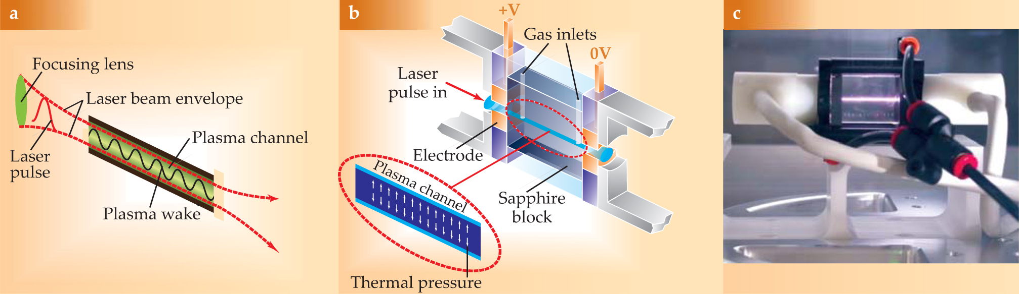
The third method of combating diffraction is to use a preformed plasma channel to guide the laser pulse (see figure 2). The method is effective over a wide range of plasma densities. Much as in an optical fiber, the density in a plasma channel is lowest along the central axis. So the laser wavefront propagates more slowly there than along the channel boundary. That flattens the otherwise curved laser wavefront and thus extends the longitudinal distance over which it stays intense.

Figure 2. Plasma channels. (a) An intense laser pulse focused on a plasma can be guided by a preformed narrow channel of plasma. The channel also prevents diffractive breakup of the laser pulse, whose primary purpose is to excite a large-amplitude plasma wave in its wake. (b) A first-generation capillary-discharge apparatus for producing a plasma channel was initially developed at the University of Oxford.
Dephasing, the second of the problematic Ds, can be understood by analogy to surfing. For surfing electrons to catch a plasma wave, either they must start out by “paddling” until they reach a speed comparable to that of the wave, or the wave must be so big that, tsunami-like, it grabs background plasma electrons. But once electrons catch the plasma wave and accelerate, they can, like surfers, outrun it after having ridden it for a certain distance, called the dephasing distance.
The 2004 experiments already mentioned 4–6 showed that by matching the dephasing distance to the length of the accelerating plasma, one can avoid the large energy spreads that dephasing tends to engender. Electrons trapped earliest on a plasma wave are accelerated to higher energy than those trapped later on the same wave. But matching acceleration length to dephasing distance shrinks the disparity. When one lets the later electrons accelerate by sliding down the wake by just the right amount, they can end up with roughly the same energy as their predecessors, because the early starters have already outrun the wave and entered a decelerating uphill phase of the wave. For n e of order 1018 cm−3, typical dephasing distances are a few centimeters.
To achieve high electron energies in a single acceleration stage requires a sufficiently low-density plasma, in which the laser pulse moves faster. Although the plasma wave’s electric field is weaker at lower density, the dephasing distance is longer. So the field pushes the electrons longer. One expects, therefore, that the net energy gain should scale like 1/n e. And indeed the expected scaling is consistent with the 2006 experiments that demonstrated the production of a GeV electron bunch. 7
Overcoming depletion, the third D, requires techniques to replenish the laser pulse’s energy, which is being sapped by conversion to plasma-wave energy as the pulse propagates. The key idea is similar to what is done in conventional accelerators: RF accelerator structures are strung together, and fresh RF power is supplied to each structure in the string. In an LPA, the length over which the plasma significantly depletes the laser energy ultimately determines the maximum length of a single accelerator stage. For high laser intensities, the depletion length is typically on the order of the dephasing length. Staging schemes for LPAs include ideas for replenishing the laser energy by coupling in a fresh high-intensity laser pulse when the previous one has been depleted. One also has to consider the propagation and reinjection of e− beams between stages.
Lasers that are modest by today’s standards (100-TW pulses delivered at 10 Hz) have produced many spectacular results in the past few years, including the GeV electron beams. Those successes have stimulated research toward the development of so-called hyperspectral radiation facilities, which would produce coherent radiation that spans the electromagnetic spectrum from x rays to IR, all from the same source. Preliminary demonstration FEL experiments using an LPA are in progress at LBNL, the University of Strathclyde in the UK, and, in Germany, at the Max Planck Institute for Quantum Optics near Munich and the University of Jena. 10 But the most challenging applications—intense FEL-based radiation sources and multi-TeV colliders for particle physics—will require exquisite e− beam quality and stability, with relative energy spreads at least an order of magnitude smaller than are currently achievable.
Controlling trapping
The main challenge for controlling the trapping of plasma background electrons arises because the phase velocity of the plasma wave is close to the speed of light. Therefore the slow background electrons are not easily trapped. Unless the wave is a giant, one must either speed up the electrons or slow down the wave. In 1996 Donald Umstadter and coworkers at the University of Michigan proposed a method for speeding up the electrons. 11 It relied on using the sideways photon pressure of an additional laser pulse propagating transversely across the plasma wave. That sideways pressure would facilitate trapping by locally boosting the velocity of a group of plasma electrons in the direction of the plasma wave.
The next year our Berkeley group, in collaboration with colleagues from the US Naval Research Laboratory, proposed an alternative scheme that relied on the beating of two intersecting laser pulses. 12 In that colliding-pulse method, two counterpropagating laser pulses intersect at a predetermined location in the plasma wave. The overlap produces an interference beat pattern with a slow phase velocity—zero if the colliding laser pulses have the same wavelength. The slow-moving beat pattern can speed up plasma electrons in the direction of the plasma wave and thus trigger trapping.
Slowing down the plasma wave is the alternative to speeding up the background electrons. In the so-called down-ramp injection method first proposed by Sergei Bulanov and coworkers in 1998, 13 an intense laser pulse is focused on a region where n e is decreasing in the direction of the laser propagation. As the laser pulse travels through the decreasing density, the wavelength of the plasma wave generated in its wake keeps increasing. That has the effect of stretching the wake so that its phase velocity is less than the velocity of the laser pulse. The wake’s phase velocity can be tuned by adjusting the rate at which the plasma density decreases to the point at which trapping occurs readily.
Using one of those trapping methods to produce a high-quality e− beam as the first stage of a multistage LPA and then injecting that beam into the plasma channel of the second stage should generate high-energy, high-quality beams for a variety of applications. Theory and simulations indicate that the absolute energy spread of the e− beam should be almost unchanged as the beam is accelerated through subsequent stages. For example, if an e− beam starting out with a 1-MeV energy spread is accelerated up to 10 GeV in stages, one should end up with a beam whose relative energy spread is only a part in 104. That’s good enough to drive an FEL in the x-ray regime. But one must make sure that each later acceleration stage, with its electrons injected from the previous stage, not degrade the beam quality by trapping additional electrons from the plasma background.
Recent progress
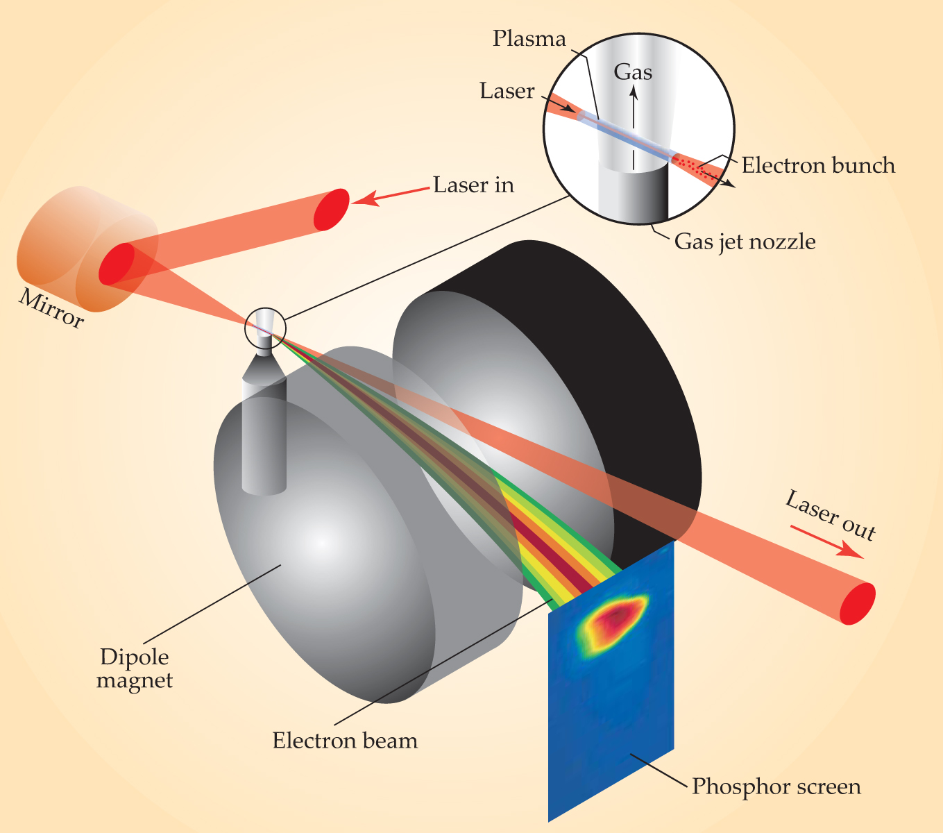
Most experiments generate a plasma wave with an intense laser pulse tightly focused on a preformed plasma or on a gas plume that the pulse rapidly ionizes (see figure 3). To characterize the e− beam emerging from the plasma, one measures its total charge, its energy spectrum, and its angular divergence. The diagnostic instruments typically include a spectrometer magnet and a phosphor screen that records the beam’s spectrum and angular spread.

Figure 3. A typical experiment in laser-driven plasma acceleration. An intense laser pulse is focused by an off-axis parabolic mirror onto the few-millimeter-wide neck of a gas jet, ionizing it locally and launching a plasma wave. The emerging electron beam accelerated by the wave is deflected by a spectrometer magnet onto a phosphor screen that reveals the beam’s energy spectrum and angular divergence.
Before 2004, experiments produced e− beams with as many as 1010 electrons and maximum energies as high as several hundred MeV. But the energy distribution within the beam was too broad, with most of the electrons at much lower energy (see figure 4). Those experiments demonstrated that high accelerating gradients were being generated. But the beams’ large angular dispersions (1°–10°) and, more important, their broad energy spreads made them unsuitable for applications requiring high beam quality—that is, low spread in phase space.

Figure 4. Before 2004, the energy spectra of electron bunches accelerated in laser-driven plasma accelerator experiments did reach as high as 100 MeV. But they were very broad (blue) and roughly exponential, with most of the electrons at much lower energy. In 2004, experiments with 10-terawatt-class pulsed lasers achieved the much narrower energy spreads (red) essential for many applications.
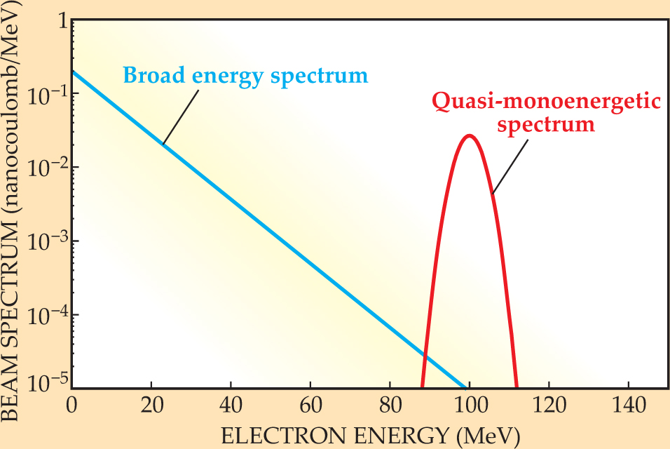
But then the groundbreaking 2004 experiments produced the first 100-MeV beams with low energy spread and low angular dispersion. 4–6 The experimenters focused powerful laser pulses into plasma or across jets of gas, blowing almost all the electrons out of a pulse’s way. That highly nonlinear “blow-out” regime, first studied in detail with computer simulations by Alexander Pukhov and Jürgen Meyer-ter-Vehn in Germany, can yield quasi-monoenergetic e− beams. 14
With plasma electron densities of order 1019 cm−3, the 2004 experiments achieved energy spreads as small as a few percent. Karl Krushelnick’s group at the UK’s Rutherford Appleton Laboratory 5 and Victor Malka’s group at the Laboratoire d’Optique Appliquée (LOA) near Paris 6 both used gas jets and laser pulses focused to spot sizes of about 25 µm. Performing the double function of ionizing the gas and launching the plasma wave in those experiments, the laser pulses maintained adequate high intensity while traversing the 2-mm-wide gas jets.
With a significantly lower-power laser more tightly focused to a spot size of 8 µm, our LBNL group used a preformed plasma channel 2 mm long to guide the drive pulse. Our 2004 results, similar to those of the other two groups, are shown in figure 5a. To obtain electron bunches with low energy spread, all three groups adjusted the plasma density so that the effective accelerator length matched the dephasing distance.

Figure 5. Energy and angular distributions of electrons accelerated in experiments like that depicted in figure
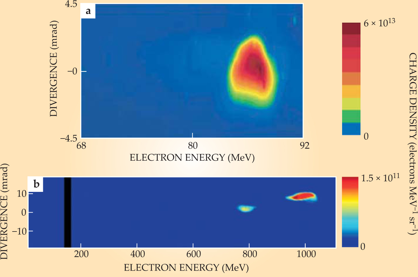
In 2006, working with Simon Hooker from the University of Oxford, we were able to demonstrate the production of high-quality beams with energies up to 1 GeV (see figure
The concept of speeding up background electrons so they can catch the plasma wave was first demonstrated by Jerome Faure and coworkers at LOA. 15 They used a laser pulse to drive a plasma wake into a 2-mm-wide gas jet. They employed a second, counterpropagating pulse to trap electrons when it overlapped with the trailing edge of the first pulse. The group produced a quasi-monoenergetic e− beam with a charge of 20 picocoulombs (108 electrons) and a 10% energy spread. With a more elaborate three-pulse configuration, it may be possible to generate femtosecond e− beam pulses with extremely low energy spread. 11
The alternative idea of trapping electrons by slowing down the plasma wave has now also been tested. 16 Cameron Geddes and coworkers at LBNL focused a 10-TW, 50-fs laser just inside the far edge of a 1-mm-wide gas jet and thus generated stable MeV electron beams, with a charge of a few hundred picocoulombs and an energy spread of 0.2 MeV. In terms of relative energy, that’s a fairly big spread. But simulations indicate that by reinjecting the beam into a subsequent plasma-channel acceleration stage, one can end up with a GeV beam with an energy spread of only 0.2 MeV.
Seeking a laser revolution
Assuming that the performance of an LPA becomes fully tunable through fine control of laser and plasma parameters and the implementation of methods to control trapping and injection, what more is needed for LPAs to become real alternatives to conventional accelerators?
Consider the formidable demands on the next-generation electron–positron collider, the International Linear Collider, which tops the particle physicists’ wish list. The 1034 s−1 cm−2 design luminosity of the ILC, an RF-driven, TeV-scale machine about 30 km long, calls for an average beam power of 14 MW. One could envision a much shorter and cheaper LPA-based TeV electron–positron collider coupling many acceleration stages together (see figure 6). The building blocks of such a collider could be 10-GeV modular accelerating stages. A TeV linac would require about 100 such stages. Each stage would consist of a preformed plasma channel, no longer than a meter, with a plasma electron density of about 1017 cm−3. Each accelerating module would be powered by a 30-J, 100-fs laser pulse that would drive a mildly nonlinear plasma wave in its wake.

Figure 6. A 2-TeV electron–positron collider based on laser-driven plasma acceleration might be less than 1 km long. Its electron arm could be a string of 100 acceleration modules, each with its own laser. A 30-J laser pulse drives a plasma wave in each module’s 1-m-long capillary channel of preformed plasma. Bunched electrons from the previous module gain 10 GeV by riding the wave through the channel. The chain begins with a bunch of electrons trapped from a gas jet just inside the first module’s plasma channel. The collider’s positron arm begins the same way, but the 10-GeV electrons emerging from its first module bombard a metal target to create positrons, which are then focused and injected into the arm’s string of modules and accelerated just like the electrons.
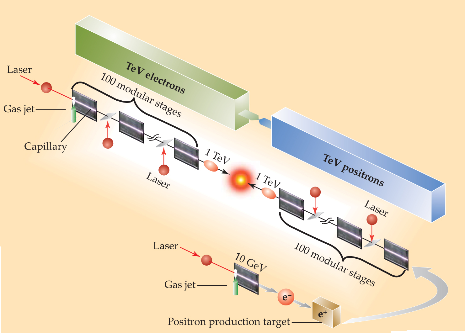
Such a wake could accelerate either electron or positron bunches. The positrons would be produced by 10-GeV electrons bombarding a metal target. The electron bunches would be created by trapping in the vicinity of a gas jet at the entrance of the first module’s plasma channel. After that initial trapping, the laser and plasma parameters must be chosen so that there is no further trapping of plasma background electrons in the rest of the first module’s channel or in any subsequent module.
After the laser pulse propagates through the plasma channel of a single module, it would have lost most of its energy. So it will be necessary to inject a fresh 30-J drive pulse into each of the 10-GeV accelerating modules. Transporting the laser pulse to the channel with conventional optics would require a 10-m distance between stages to avoid having excessive light intensity damage the focusing optics. That 10-m spacing would greatly lengthen the overall machine and thus reduce its average accelerating gradient—a key figure of merit. To avoid that, the LPA community is exploring novel concepts that would allow the spacing between stages to be less than a meter.
Several groups around the world, including ours, plan to explore those and other issues using petawatt laser systems with repetition rates as high as 10 Hz. Spurring that effort is the commercial development—most notably in France—of sophisticated petawatt-class systems.
To achieve the desired collider luminosity, a laser–plasma collider would need a repetition rate of about 15 kHz. That means an average laser power of half a megawatt per module, which is still far beyond the performance of today’s lasers. Current high-peak-power lasers can operate with an average power of 100 W at most, with a wall-plug efficiency of about 0.1%.
On a less grandiose scale than TeV colliders, LPAs offer attractive prospects for driving light sources. Their potential advantages over light sources based on conventional linacs include compactness and cost, intrinsic synchronization between the e− beams and drive-laser pulses, and the femtosecond duration of the e− beam pulses. But the relatively low average laser power of today’s high-peak-power lasers places severe limitations on the average power of the electron beam and therefore on the brightness of the radiation.
From various quarters, there’s considerable emphasis on creating more capable pulsed lasers. High-average-power diode pump lasers and new amplifier materials based on ceramics are being developed for military and civil applications. Laser systems operating in so-called burst mode (a few seconds active, followed by minutes of cooling) have approached 100-kW average power, but not yet the operating parameters needed for LPAs. Diode-based lasers are being developed to reach greater than 50% wall-plug efficiency, which would be essential for both light-source and collider applications.
The ever-increasing performance of laser systems has contributed much to the blossoming of laser-driven plasma acceleration over the past decade. So has the increasing power of computer simulation and, of course, the development of ingenious concepts for mastering the physics of laser–plasma interactions. We believe that short-term applications such as ultrafast hyperspectral radiation sources will soon come to fruition. Reaching the high average-power levels required for particle-physics colliders is a daunting but not insurmountable task that requires a revolution in laser technology.
We thank all past and present members of the LOASIS program at LBNL, especially Csaba Toth, Carl Schrveder, and Cameron Geddes, for their contributions to this article.
References
1. T. Tajima, J. M. Dawson, Phys. Rev. Lett. 43, 267 (1979). https://doi.org/10.1103/PhysRevLett.43.267
2. For a review, see E. Esarey et al., IEEE Trans. Plasma Sci. 24, 252 (1996). https://doi.org/10.1109/27.509991
3. C. E. Clayton et al., Phys. Rev. Lett. 54, 2343 (1985). https://doi.org/10.1103/PhysRevLett.54.2343
4. C. G.R. Geddes et al., Nature 431, 538 (2004). https://doi.org/10.1038/nature02900
5. S. P. D. Mangles et al., Nature 431, 535 (2004). https://doi.org/10.1038/nature02939
6. J. Faure et al., Nature 431, 541 (2004). https://doi.org/10.1038/nature02963
7. W. P. Leemans et al., Nat. Phys. 2, 696 (2006). https://doi.org/10.1038/nphys418
8. I. Blumenfeld et al., Nature 445, 741 (2007). https://doi.org/10.1038/nature05538
9. C. Joshi, Phys. Plasmas 14, 055501 (2007). https://doi.org/10.1063/1.2721965
10. H. -P. Schlenvoigt et al., Nat. Phys. 4, 130 (2008). https://doi.org/10.1038/nphys811
11. D. Umstadter, J. K. Kim, E. Dodd, Phys. Rev. Lett. 76, 2073 (1996). https://doi.org/10.1103/PhysRevLett.76.2073
12. E. Esarey et al., Phys. Rev. Lett. 79, 2683 (1997). https://doi.org/10.1103/PhysRevLett.79.2682
13. S. V. Bulanov et al., Phys. Rev. E 58, R5257 (1998). https://doi.org/10.1103/PhysRevE.58.R5257
14. A. Pukhov, J. Meyer-ter-Vehn, Appl. Phys. B 74, 355 (2002). https://doi.org/10.1007/s003400200795
15. J. Faure et al., Nature 444, 737 (2006). https://doi.org/10.1038/nature05393
16. C. G. R. Geddes et al., Phys. Rev. Lett. 100, 215004 (2008). https://doi.org/10.1103/PhysRevLett.100.215004
17. A. Butler, D. J. Spence, S. M. Hooker, Phys. Rev. Lett. 89, 185003 (2002). https://doi.org/10.1103/PhysRevLett.89.185003
More about the authors
Wim Leemans heads the LOASIS (Lasers, Optical Accelerator Systems Integrated Studies) program at the Lawrence Berkeley National Laboratory in Berkeley, California. Eric Esarey is the program’s deputy head.
Wim Leemans, Lawrence Berkeley National Laboratory, Berkeley, California, US .
Eric Esarey, Lawrence Berkeley National Laboratory, Berkeley, California, US .


