From the archives: The stability of the bicycle
DOI: 10.1063/1.2364246
Almost everyone can ride a bicycle, yet apparently no one knows how they do it. I believe that the apparent simplicity and ease of the trick conceals much unrecognized subtlety, and I have spent some time and effort trying to discover the reasons for the bicycle’s stability. Published theory on the topic is sketchy and presented mainly without experimental verification. In my investigations I hoped to identify the stabilizing features of normal bicycles by constructing abnormal ones lacking selected features (see figure 1). The failure of early unridable bicycles led me to a careful consideration of steering geometry, from which—with the aid of computer calculations—I designed and constructed an inherently unstable bicycle.

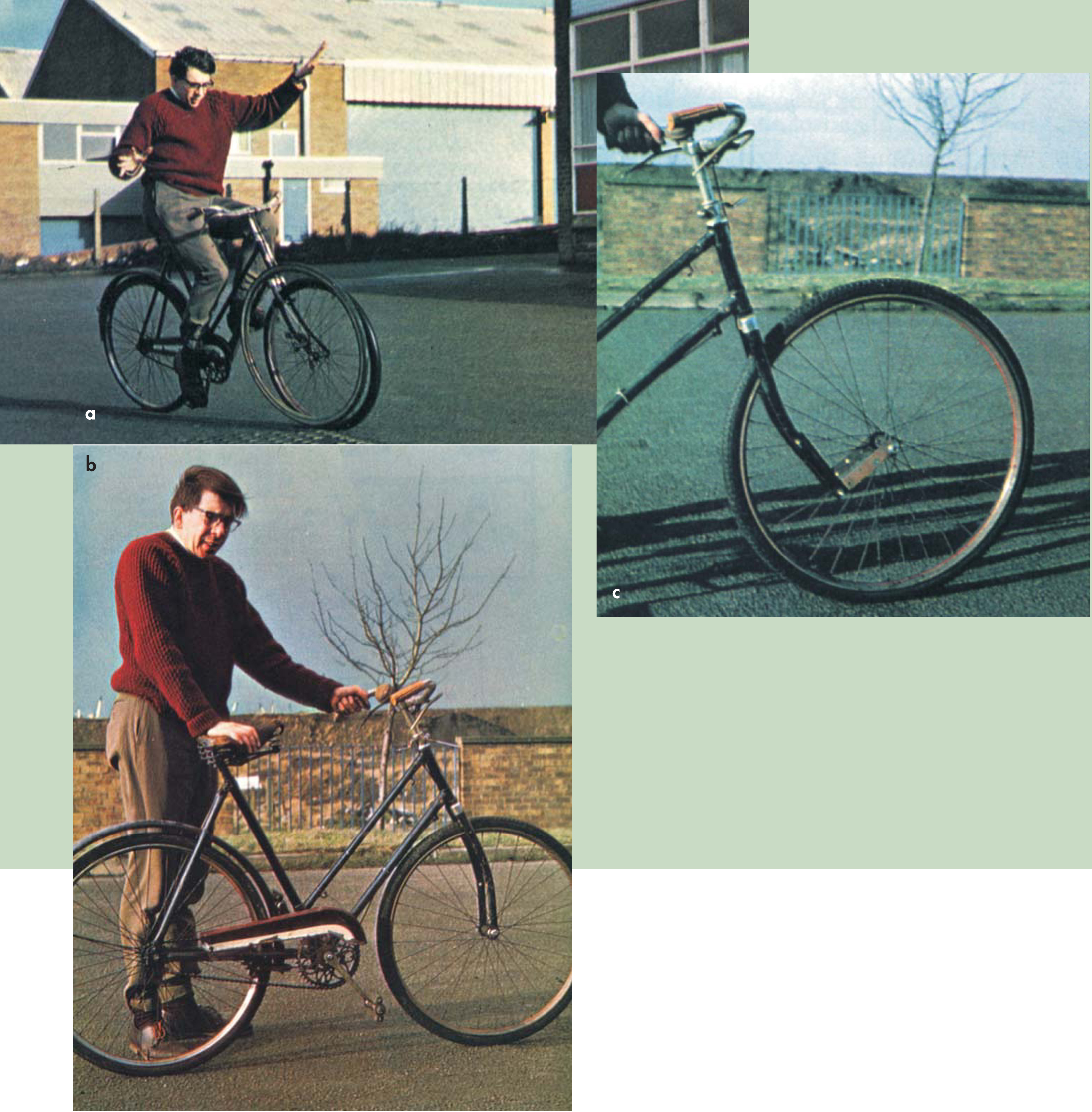
Figure 1. Unridable bicycles. David Jones is seen here with three of his experimental machines, two of which turned out to be ridable after all. (a) At the top of this page is URB I, with its extra counter-rotating front wheel that tests the gyroscopic theories of bicycle stability. (b) At left is URB III, whose reversed front forks give it great stability when pushed and released riderless. (c) URB IV (immediately above) has its front wheel mounted ahead of the usual position and comes nearest to being “unridable.”
The nature of the problem
Most mechanics textbooks or treatises on bicycles either ignore the matter of their stability or treat it as fairly trivial. The bicycle is assumed to be balanced by the action of its rider who, if he feels the vehicle falling, steers into the direction of fall and so traverses a curved trajectory of such a radius as to generate enough centrifugal force to correct the fall. This theory is well formalized mathematically by S. Timoshenko and D. H. Young, 1 who derive the equation of motion of an idealized bicycle, neglecting rotational moments, and demonstrate that a falling bicycle can be saved by proper steering of the front wheel. The theory explains, for example, that the ridability of a bicycle depends crucially on the freedom of the front forks to swivel (if they are locked, even dead ahead, the bicycle can not be ridden), that the faster a bicycle moves the easier it is to ride (because a smaller steering adjustment is needed to create the centrifugal correction), and that it can not be balanced when stationary.
Nevertheless this theory can not be true, or at least it can not be the whole truth. You experience a powerful sense, when riding a bicycle fast, that it is inherently stable and could not fall over even if you wanted it to. Also a bicycle pushed and released riderless will stay up on its own, traveling in a long curve and finally collapsing after about 20 seconds, compared to the 2 seconds it would take if static. Clearly the machine has a large measure of self-stability.
The next level of sophistication in current bicycle-stability theory invokes the gyroscopic action of the front wheel. If the bike tilts, the front wheel precesses about the steering axis and steers it in a curve that, as before, counteracts the tilt. The appeal of this theory is that its action is perfectly exemplified by a rolling hoop, which indeed can run stably for just this reason. A bicycle is thus assumed to be merely a hoop with a trailer.
The lightness of the front wheel distresses some theorists, who feel that the precession forces are inadequate to stabilize a heavily laden bicycle. 2,3 K. I. T. Richardson 4 allows both theories and suggests that the rider himself twists the front wheel to generate precession, hence staying upright. A theory of the hoop and bicycle on gyroscopic principles is given by R. H. Pearsall 5 who includes many rotational moments and derives a complex fourth-order differential equation of motion. This is not rigorously solved but demonstrates on general grounds the possibility of self-righting in a gyroscopically stable bicycle.
A non-gyroscopic bicycle
It was with vague knowledge of these simple bicycle theories that I began my series of experiments on bicycle stability. It occurred to me that it would be fun to make an unridable bicycle, which by canceling the forces of stability would baffle the most experienced rider. I therefore modified a standard bicycle by mounting on the front fork a second wheel, clear of the ground, arranged so that I could spin it against the real front wheel and so oppose the gyroscopic effect. This creation, “Unridable Bicycle MK I” (URB I), unaccountably failed; it could be easily ridden, both with the extra wheel spinning at high speed in either direction and with it stationary. Its “feel” was a bit strange, a fact I attributed to the increased moment of inertia about the front forks, but it did not tax my (average) riding skill even at low speeds. The result resolves the ambiguity admitted by Richardson: The gyroscopic action plays very little part in the riding of a bicycle at normally low speeds.
This unexpected result puzzled me. If the bicycle, as seemed likely, is a hoop with a trailer but is not gyroscopic, perhaps the hoop is not gyroscopic either? I repeated the experiment of URB I on a hoop by constructing one with an inner counter-rotating member, and this collapsed gratifyingly when I tried to roll it. The hoop is a bona fide gyroscope.
Then I tried to run URB I without a rider, and its behavior was quite unambiguous. With the extra wheel spinning against the road wheels, it collapsed as ineptly as my non-gyroscopic hoop; with it spinning the same way it showed a dramatic slow-speed stability, running uncannily in a slow, sedate circle before bowing to the inevitable collapse.
These results almost satisfied me. The light, riderless bicycle is stabilized by gyroscopic action, whereas the heavier ridden model is not—it requires constant rider effort to maintain its stability. A combination of the simple theories accounts neatly for all the facts. But the problem of why a ridden bicycle feels so stable, if in fact it is not, remains. There was one more crucial test: Could URB I be ridden in its disrotatory mode “hands off”? For about the only sensible theory for riding with “no hands” supposes that the rider tilts the frame by angular body movements and thus steers by the resulting front-wheel precession. 3
Gingerly, and with great trepidation, I tried the experiment—downhill, to avoid complicating the effort with pedaling. URB I is not an easy bicycle to ride “hands off” even with the front wheel static; it somehow lacks balance and responsiveness. In the disrotatory mode it was almost impossible and invited continual disaster, but it could, just, be done. I was thus led to suspect the existence of another force at work in the moving bicycle.
More theories
In the preliminary stages of this investigation, I had pestered all my acquaintances to suggest a theory of the bicycle. Apart from the two popular theories that I have mentioned already, I obtained four others, which I shall call theories 3, 4, 5, and 6:
The bicycle is kept upright by the thickness of its tires (that is, it is a thin steamroller).
When the bicycle leans, the point of contact of the front tire moves to one side of the plane of the wheel, creating a frictional torque twisting the wheel into the lean and stabilizing the bicycle, as before, by centrifugal action.
The contact point of the bicycle’s front tire is ahead of the steering axis. Turning the front wheel therefore moves the contact point with the turn, and the rider uses this effect, when he finds himself leaning, to move his baseline back underneath his center of gravity.
The contact point of the bicycle’s tire is behind the steering axis. As a result, when the bicycle leans a torque is developed that turns the front wheel.
I suspect that theory 3 is not really serious. Theories 5 and 6 raise the question of steering geometry, which I was later to look at in this work—note that the gyro theory is silent on why all front forks are angled and all front forks project forward from them. To test this matter I made URB II.
URB II had a thin front wheel, only one inch in diameter (an adapted furniture castor) mounted dead in line with the steering axis, to test any steering-geometry theory. It looked a ludicrous contraption. URB II was indeed hard to ride, and collapsed readily when released, but this was at least in part because it could negotiate no bump more than half an inch high. The little front wheel also got nearly red hot when traveling fast.
I abandoned URB II as inconclusive, but preferred theory 6 to theory 5, because in all actual bicycles the front wheel’s contact point is behind the intersection of the steering axis with the ground. Theory 6 is also advocated by the only author who supports his hypothesis with actual measurements. 6 But I could not see why this force should vanish, as it has to, once the bicycle is traveling in its equilibrium curve. I had grave suspicions of theory 4, for surely this torque acting across less than half the width of the tire would have a very small moment, and would depend crucially on the degree of inflation of the tire. Besides, I did not want nasty variable frictional forces intruding into the pure, austere Newtonian bicycle theory towards which I was groping.
Steering geometry
The real importance of steering geometry was brought home to me very dramatically. I had just completed a distressing series of experiments involving loading URB I, with or without its extra gyro wheel, with some 30 pounds of concrete slabs and sending it hurtling about an empty parking lot (there are some tests one can not responsibly carry out on public roads). The idea was to see if the extra weights—projecting from the front of the frame to have the maximal effect on the front wheel—would prevent the gyro effect from stabilizing the bicycle, as anticipated from the difference between ridden and riderless bikes. It appeared that the weights made the bicycle a little less stable, and the counter-rotating wheel still threw it over almost immediately. But the brutal effects on the hapless machine as it repeatedly crashed to earth with its burden had me straightening bent members and removing broken spokes after almost every run.
It occurred to me to remove the handlebars to reduce the moment of inertia about the steering axis; this meant removing the concrete slabs and the brake assembly, which incidentally enabled the front wheel to be turned through 180° on the steering axis, reversing the front-fork geometry (see figure 2). I had tried this experiment once before, calling the result URB III; that machine had been strangely awkward to wheel or ride, and I had noted this result as showing that steering geometry was somehow significant. Idly I reversed the forks of the bike and pushed it away, expecting it to collapse quickly. Incredibly, it ran on for yards before falling over! Further tests showed that this new riderless bicycle was amazingly stable. It did not merely run in a curve in response to an imposed lean, but actively righted itself—a thing no hoop or gyro could do. The bumps and jolts of its progress did not imperil it, but only as it slowly lost speed did it become unstable. Then it often weaved from side to side, leaning first one way and then the other before it finally fell over. This experiment convinced me that the forces of stability were “hunting”—overcorrecting the lean at each weave and ultimately causing collapse. Once or twice the riderless disrotatory URB I had shown momentary signs of the same behavior in its brief doomed career.

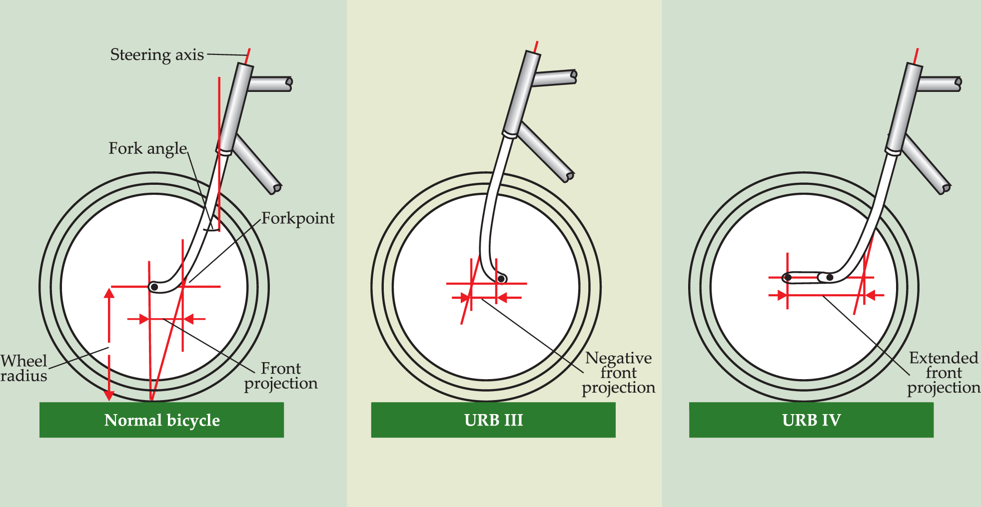
Figure 2. Front-fork geometry. On the left is a normal bicycle. The center shows URB III with reversed forks giving a negative front projection, and on the right is URB IV with extended front projection.
Why does steering geometry matter? One obvious effect is seen by wheeling a bicycle along, holding it only by the saddle. It is easy to steer the machine by tilting the frame, when the front wheel automatically steers into the lean. This is not a gyroscopic effect, because it occurs even if the bike is stationary. A little study shows that it occurs because the center of gravity of a tilted bicycle can fall if the wheel twists out of line. So here was a new theory of bicycle stability—the steering is so angled that as the bike leans, the front wheel steers into the lean to minimize the machine’s gravitational potential energy. To check this theory I had to examine the implications of steering geometry very seriously indeed.
Computerized bicycles
It turns out that defining the height of the forkpoint of a bicycle in terms of the steering geometry and angles of lean and of steer (figure 3) is a remarkably tricky little problem. In fact I gave it up after a few attempts and instead wrote a Fortran subroutine, “BICYC,” that solved the simultaneous trigonometrical equations iteratively and generated all the required dimensions for me. Armed with BICYC, I could now create all sorts of mad bicycles on the computer and put them through their steer-and-lean paces. The first few runs were most encouraging; they showed that with normal bicycle geometry, tilting the frame did indeed ensure that the center of gravity had its minimal elevation with the wheel twisted into the tilt. This had the makings of a really good theory. I hoped to prove that, for the observed steering geometry, the steering angle for minimal center-of-gravity height increased with the angle of lean by just the factor needed to provide perfect centrifugal stability, and that was why all bicycles have more or less the same steering geometry. As for the strange behavior of URB III, awkward to ride but incredibly stable if riderless, perhaps BICYC would provide a clue.

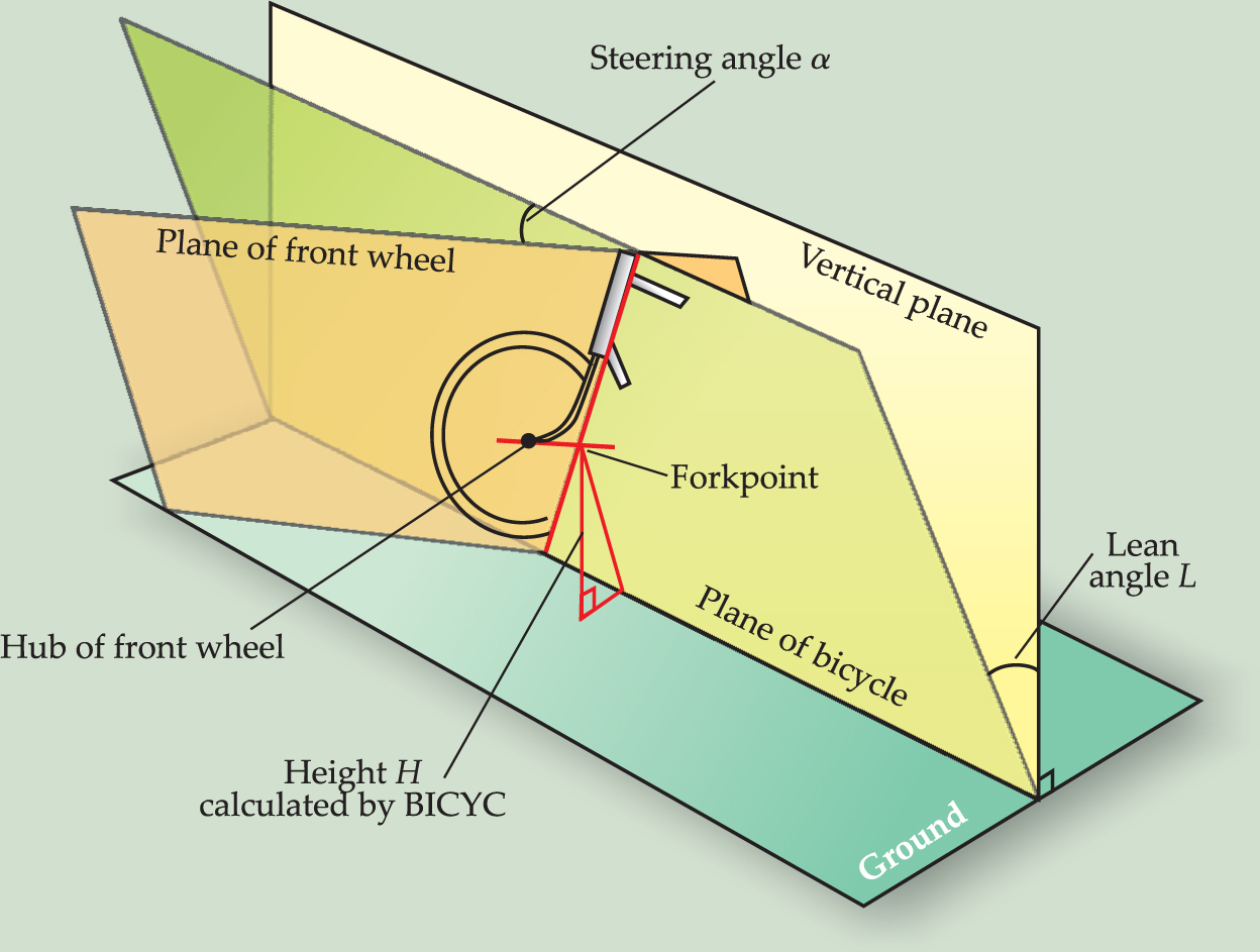
Figure 3. A tricky trigonometrical problem. We need to know H, the height of the forkpoint from the ground, for a leaning bicycle. Subroutine BICYC calculates both the vertical height and the height in the plane of the bike.
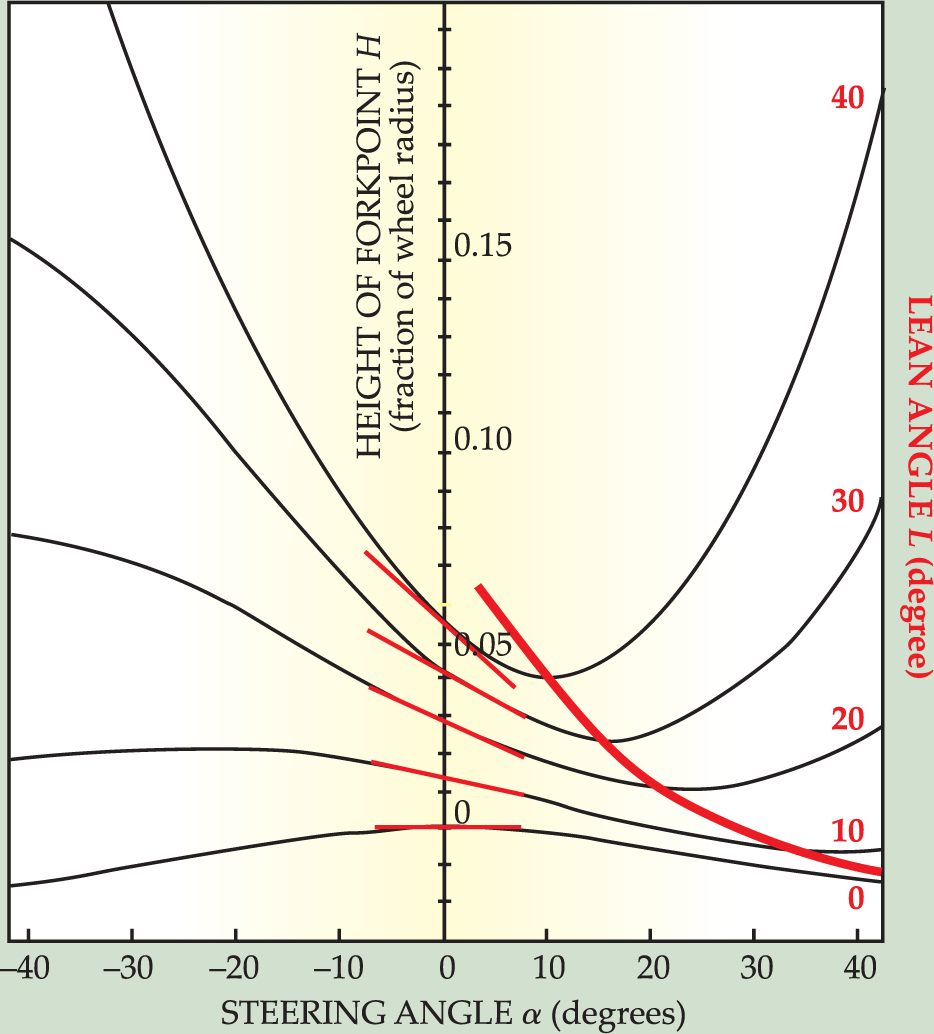
But further calculations shattered my hopes. Even with the bicycle dead upright, the forkpoint fell as the wheel turned out of plane (thus neatly disproving the contention of reference that a bicycle tends to run true because its center of gravity rises with any turn out of plane), and the minimal height occurred at an absurdly large steering angle, 60°. Even worse, as the bike tilted, this minimum occurred at angles nearer and nearer the straight-ahead position (figure 4) until at 40° of tilt the most stable position was only 10° out of plane (these values are all for a typical observed steering geometry). Clearly the tilting wheel never reaches its minimal-energy position, and the minimum can not be significant for determining the stability of the bicycle.

Figure 4. Computerized bicycles. These data, from BICYC output, show that the minimal height of the forkpoint occurs nearer to the straight-ahead position for greater angles of lean. Note also that dH/dα varies linearly with lean angle L for small L. Curves, computed for typical steering geometry (20° radii front projection), are vertically staggered for clarity.
I looked instead at the slope of the height versus steering-angle curve at zero steering angle, because this slope is proportional to the twisting torque on the front wheel of a tilted bike. Then, if H is the height of the forkpoint, the torque varies as –dH/dα at small values of α, the steering angle.
The curves in figure 4 show clearly that dH/dα varies linearly with lean angle L for small angles of lean. The more the bike leans, the bigger is the twisting torque, as required. The constant of proportionality for this relationship is d 2 H/dαdL, and the sign convention I adopted implies that a bicycle is stable if this parameter is negative. That is, for stability the forkpoint falls as the wheel turns into the lean when the bike is tilted.
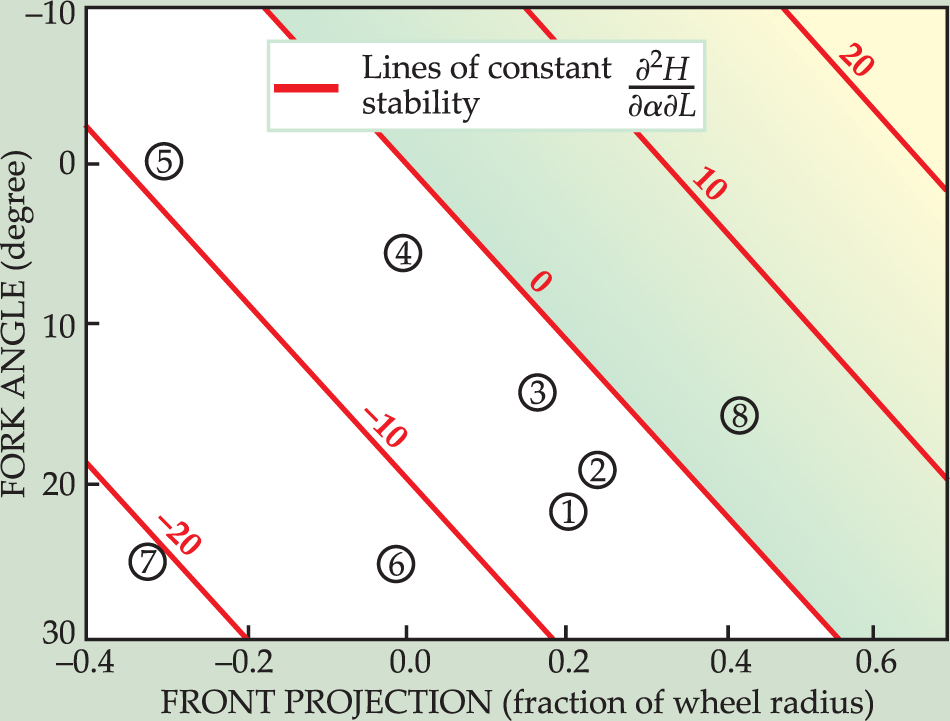
I therefore computed d 2 H/dαdL for a wide range of steering geometries, and drew lines of constant stability on a diagram connecting the two parameters of steering geometry—the angle of the front-fork steering axis and the projection of the wheel center ahead of this axis. I then plotted on my stability diagram all the bicycles I could find—ranging from many existing models to old high-wheeled “penny-farthings” to see if they supported the theory.
The results (figure 5) were immensely gratifying. All the bicycles I plotted have geometries that fall into the stable region. The older bikes are rather scattered but the modern ones are all near the onset of instability defined by the d 2 H/dαdL = 0 line. This is immediately understandable. A very stable control system responds sluggishly to perturbation, whereas one nearer to instability is more responsive; modern bicycle design has emphasized nimbleness and maneuverability. Best of all, URB III comes out much more stable than any commercial bike. This result explains both its wonderful self-righting properties and also why it is difficult to ride—it is too stable to be steered. An inert rider with no balancing reflexes and no preferred direction of travel would be happy on URB III, but its characteristics are too intense for easy control.

Figure 5. Stable and unstable bicycles. On this plot of fork angle versus front projection the d 2 H/dαdL lines are lines of constant stability. Shaded area shows the unstable region. Point 1 is a normal modern bicycle; 2 is a racing bike. Points 3 and 4 are high-wheelers (or “penny-farthings”) from the 1870s. Point 5 is an 1887 Rudge machine, and 6 is a Lawson “Safety” of 1879. Point 7 is URB III, and point 8, the only unstable bicycle, is of course URB IV.
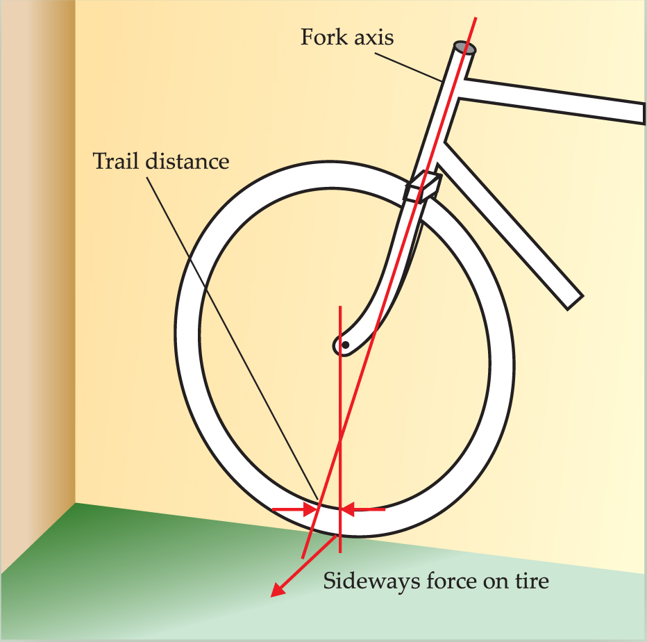
This mathematical exercise also made it plain that the center-of-gravity lowering torque is developed exactly as shown in figure 6, and is identical with that postulated in reference . But it does not vanish when the bicycle’s lean is in equilibrium with centrifugal force, as therein supposed (BICYC calculated the height of the forkpoint in the plane of the bicycle—the “effective vertical”—to allow for this). It can only vanish when the contact point of the front wheel is intersected by the steering axis, which BICYC shows clearly is the condition for minimal height. There is thus an intimate connection between the “trail” of a bicycle, as defined in figure 6, and d 2 H/dαdL; in fact the d 2 H/dαdL line in figure 4 coincides with the locus of zero trail.

Figure 6. Sideways force on front tire produces a torque about the steering axis, so tending to lower the center of gravity of the bicycle.
Two further courses of action remained. First, I could make URB IV with a steering geometry well inside the unstable region, and second, I had to decide what force opposes the twisting torque on a bike’s front wheel and prevents it reaching BICYC’s predicted minimal center-of-gravity position.
Self-centering
Let us consider the second point first; I was looking for some sort of self-centering in a bicycle’s steering. Now this is well known in the case of four-wheeled vehicles: self-centering is built into all car steering systems, and various self-righting torques such as “pneumatic trail” are described by automobile engineers. Once again nasty variable frictional forces were rearing their ugly heads! But how could I check whether a bicycle wheel has self-centering? I examined a child’s tricycle for this property, releasing it at speed and, running alongside it, giving the handlebars a blow. It certainly seemed to recover quickly and continue in a straight line, but unfortunately the tricycle (being free of the requirement of two-wheeled stability) has a different steering geometry.
So I made an experimental fixed-lean bicycle by fastening an extra “outrigger” wheel to the rear of the frame, converting it to an asymmetric tricycle. Adjustment of the outrigger anchorage could impose any angle of lean on the main frame. This machine was very interesting. Initially I gave it 15° of lean, and at rest the front wheel tilted to the 40° angle predicted by BICYC. When in motion, however, the wheel tended to straighten out, and the faster the bike was pushed the straighter did the front wheel become. Even if the machine was released at speed with the front wheel dead ahead it turned to the “equilibrium” angle for that speed and lean—another blow for gyro theory, for with the lean fixed there can be no precessional torque to turn the wheel. So clearly there is a self-centering force at work. It is unlikely to be pneumatic trail, for the equilibrium steering angle for given conditions appears unaltered by complete deflation of the front tire. Now I had encountered a very attractive form of self-centering action, not depending directly on variable frictional forces, while trying the naive experiment of pushing a bicycle backwards. Of course it collapsed at once because the two wheels travel in diverging directions. In forward travel the converse applies and the paths of the two wheels converge. So, if the front wheel runs naturally in the line of its own plane, the trailing frame and rear wheel will swing into line behind it along a tractrix, by straightforward geometry. To an observer on the bike, however, it will appear that self-centering is occurring (though it is the rest of the bike and not the front wheel that is swinging).
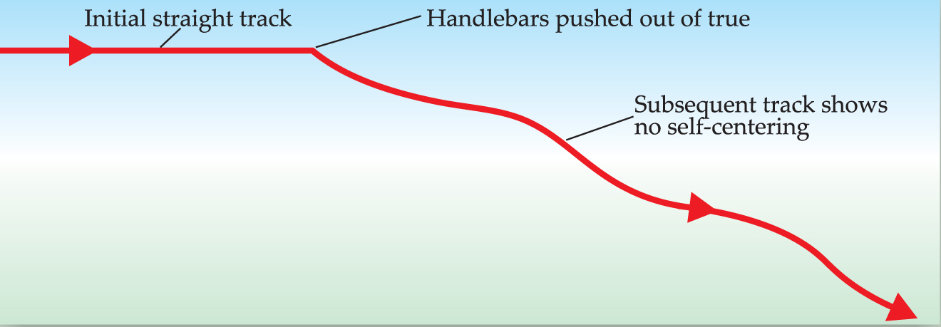
I modified my outrigger tricycle to hold the main frame as nearly upright as possible, so that it ran in a straight line. Then, first soaking the front wheel in water to leave a track, I pushed it up to speed, released it, and, running alongside, thumped the handlebars out of true. Looking at the bike, it seemed evident that the wheel swung back to dead ahead. But the track (figure 7) showed what I hoped to find—a sharp angle with no trace of directional recovery. The bicycle has only geometrical castor stability to provide its self-centering.

Figure 7. Self-centering? A bicycle with an “outrigger” third wheel to keep it upright was pushed and released riderless. At the point shown the handlebars were knocked out of true, resulting in a change of direction and no self-centering. The slight wave in the track resulted from oscillations in the framework.
Success at last!
This test completed the ingredients for a more complete theory of the bicycle. In addition to the rider’s skill and the gyroscopic forces, there are, acting on the front wheel, the center-of-gravity lowering torque (figure 6) and the castoring forces; the heavier the bicycle’s load the more important these become. I have not yet formalized all these contributions into a mathematical theory of the bicycle, so perhaps there are surprises still in store; but at least all the principles have been experimentally checked.
I made URB IV by moving the front wheel of my bicycle just four inches ahead of its normal position, setting the system well into the unstable region. It was indeed very dodgy to ride, though not as impossible as I had hoped—perhaps my skill had increased in the course of this study. URB IV had negligible self-stability and crashed gratifyingly to the ground when released at speed.
It seems a lot of tortuous effort to produce in the end a machine of absolutely no utility whatsoever, but that sets me firmly in the mainstream of modern technology. At least I will have no intention of foisting the product onto a long-suffering public in the name of progress.
References
1. S. Timoshenko, D. H. Young, Advanced Dynamics, McGraw-Hill, New York (1948), p. 239.
2. A. Gray, A Treatise on Gyrostatics and Rotational Motion, Dover, New York (1959), p. 146.
3. J. P. den Hartog, Mechanics, Dover, New York (1961), p. 328.
4. K. I. T. Richardson, The Gyroscope Applied, Hutchinson, London (1954), p. 42.
5. R. H. Pearsall, Proc. Inst. Automobile Eng. 17, 395 (1922).
6. R. A. Wilson-Jones, Proc. Inst. Mech. Eng. (Automobile division), 1951–52, p. 191.
7. Encyclopaedia Britannica (1957 edition), entry under “Bicycle.”
More about the authors
David E. H. Jones took bachelor’s and doctor’s degrees in chemistry at Imperial College, London. When this article first appeared, he was a spectroscopist at ICI in England.
David E. H. Jones, Imperial College, London.


