Superhydrophobic surfaces reduce drag
DOI: 10.1063/1.3248460
Turbulent flows of a liquid along a wall experience frictional drag, a macroscopic phenomenon that strongly affects the efficiency, costs, and other parameters of countless engineering systems—from marine vessels to oil pipelines. The drag arises from shear stress, the rate per unit area of momentum transfer from the flow to the wall. To reduce the shear stress, engineers could add polymers to the flow, inject bubbles against the surface, or combine the two methods. But those approaches bear their own costs.
Researchers led by Jonathan Rothstein at the University of Massachusetts Amherst now offer a proof-of-principle demonstration of a new, passive option for reducing drag in a turbulent flow. 1 They tailored the microscale structure of a hydrophobic material—polydimethylsiloxane (PDMS), akin to the rubbery polymer used to caulk bathtubs—to create air pockets that allow the flow to “slip” (shear free) at the liquid–air interface. The greater the area covered by air pockets, the greater the overall reduction in shear stress—up to 50%, the researchers estimate, judging from particle-image velocimetry and pressure-drop experiments over a wide range of Reynolds numbers.
The physics behind the effect goes back nearly two centuries. Since the 1820s, evidence began mounting that fluids come to a virtual standstill at a solid surface, at least macroscopically. In 1904 Ludwig Prandtl interpreted that no-slip condition as an effect of friction, which causes layers of fluid immediately adjacent to a wall to stick to its surface. Frictional effects, he argued, were thus experienced in a thin boundary layer near the wall. Outside that boundary layer, the flow was essentially inviscid, and friction could be considered negligible (see the article by John D. Anderson Jr in PHYSICS TODAY, December 2005, page 42 ).
A century of experiments have borne out Prandtl’s theory. Viscous effects in the turbulent regime, it turns out, are mostly restricted to a thin region inside the boundary layer, known as the viscous sublayer. And velocity gradients normal to the surface—the source of the shear stress—can indeed be enormous over very short distances. For hydro-phobic surfaces, the approach to reducing drag thus boils down to reducing the liquid–solid contact area that generates it. Because the viscosity of air is far smaller than that of water, it moves easily and the liquid–air interface maintains a slip velocity close to that of the bulk fluid.
The rough and the smooth
Rough surfaces are far more common in nature (and on ships’ hulls) than smooth ones. Fortunately, the combination of roughness and hydrophobicity—the property that prompts water to bead up into a near-spherical ball on a lotus leaf, for instance—also lowers the free energy of an air–water interface such that surface tension can support the liquid layer between neighboring peaks.
To systematically investigate the drag reduction conferred by such super-hydrophobic surfaces—that is, ones both rough and hydrophobic—in both laminar and turbulent flow regimes, the UMass team lithographically produced a 1-m-long surface having corrugated ridges in their PDMS (see figure 1). They then fashioned a 15-mm-deep flow channel—a rectangular pipe whose bottom held the corrugated PDMS surface and whose top was made from smooth, transparent acrylic. To monitor the fluid’s velocities throughout the channel and to within 50 µm of its surface, they seeded the flow with neutrally buoyant silvered glass spheres, illuminated a plane of the channel using laser light, and captured the motion on video camera.

Figure 1. A periodic array of microscopic ridges or grooves in a hydrophobic surface creates a heterogeneous interface, part liquid–solid and part liquid-air, when a column of water flows over the top (and into the page). University of Massachusetts Amherst researchers considered two geometries: one in which the width w of each pocket and the spacing d between them is 30 µm, and one in which w and d are both 60 µm (the height h is 25 µm in both cases). Both geometries contain a 50% shear-free interface.
(Adapted from ref. 1)
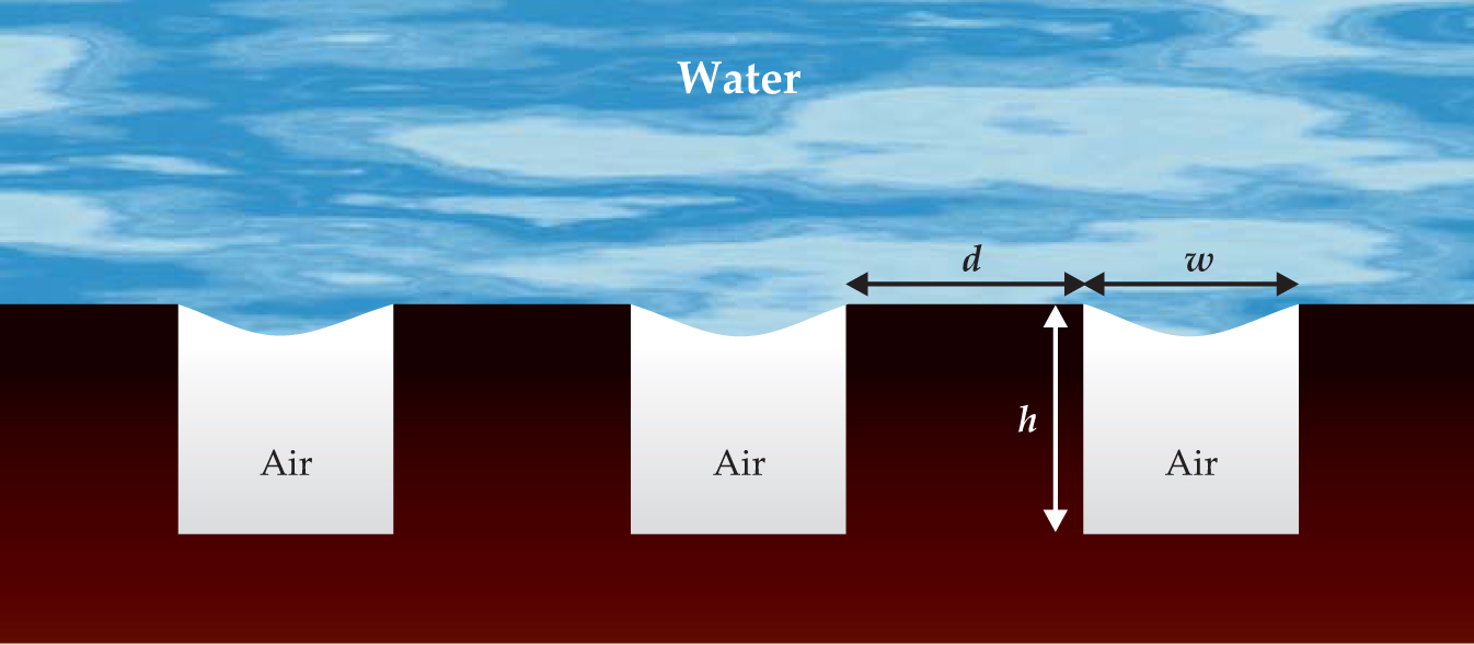
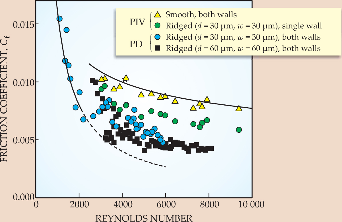
Figure 2 illustrates the dramatic drop in the coefficient of friction Cf deduced from those particle-image velocimetry measurements and from separately run pressure-drop measurements along a channel. In the turbulent regime—at Reynolds numbers above 2100 in this case—frictional drag was observed to dramatically decrease as smooth surfaces were swapped for superhydrophobic ones. Indeed, the critical Reynolds number at which the onset of drag reduction occurs is related to the ratio of two length scales—one associated with the geometry of the surface corrugations, the other with the thickness of the viscous sublayer.

Figure 2. The coefficient of friction C f refers to the shear stress at a wall divided by the kinetic energy density of the flow and is plotted here for various surfaces as a function of Reynolds number. Solid lines indicate the predicted C f along a smooth channel when the flow is laminar (the leftmost curve) and when it becomes turbulent (topmost curve). Data sets are distinguished by whether they are calculated from particle-velocimetry measurements (PIV) or from pressure drops (PD) observed along the channel. The onset of drag reduction occurs in the turbulent regime where the height of the viscous sublayer (about 50 µm) is on the scale of the surface corrugations. Moreover, their effect becomes increasingly pronounced as their width and spacing increase and as both walls (top and bottom) of a rectangular flow channel are made hydrophobic.
(Adapted from ref. 1)
The Reynolds number is a dimensionless number frequently interpreted as the ratio of inertial to viscous terms in the Navier–Stokes equations. At low Reynolds numbers, viscous forces dominate throughout the channel and the flow is silky smooth, or laminar. It’s no surprise, then, that for laminar flow, the drag-reducing effect of microscopic ridges under a macroscopically deep (15-mm) channel is minimal—about 1%, the researchers estimate. That’s not to say drag can’t be reduced in laminar flows by the use of superhydrophobic walls. It can, and by an equally dramatic amount, but only in the context of microfluidics, in which the size of the corrugations is on the same order as the channel depth. 2
At the high Reynolds numbers characteristic of the turbulent regime, inertial forces dominate. Indeed, they pervade the entire channel except for the thin viscous sublayer closest to the wall. That sublayer, just 100 µm thick in the UMass system, becomes thinner (to about 50 µm) as the Reynolds number increases and is the only part of the channel that transfers momentum to the wall.
The efficient mixing of fluid layers and greater shear stress are responsible for the jump in the friction coefficient as the flow changes from smooth to turbulent and for the emergence of a veritable zoo of coherent structures such as the ones shown on this month’s cover. The tangles and swirling eddies are thought to form in the boundary layer and slowly percolate into the bulk fluid.
Rothstein’s UMass colleague Blair Perot and graduate student Michael Martell found those structures in numerical simulations of the fluid’s path and velocity in flow channels modeled on the experiments (though with flow-channel depth an order of magnitude smaller). 3 Their calculations complement the experimental results. The velocity of water is constrained to be zero at the top of each ridge, but finite slip velocities emerge from the Navier-Stokes equations along the air–water interface. The topology of the surface, the simulations suggest, affects not just the drag reduction—with increased spacing between ridges producing greater slip velocities—but also the location of the turbulent eddies, the mean shear, and the energy dissipation.
Toward practical systems
Should we expect to see superhydrophobic surfaces grace the hulls of ships anytime soon? Research is far from addressing practicalities: The UMass experiments explored flow speeds under 1.5 m/s (3 knots), at pressures under 5 kPa (0.5 m of water), and at Reynolds numbers under 10 000. Supertankers have Reynolds numbers in the tens of millions, but with viscous-sublayer thicknesses comparable to those in the UMass experiments.
Nevertheless, Rothstein is optimistic. “In 1987, 3M coated an America’s Cup yacht with a plastic film embedded with riblets,” minute, v-shaped grooves that also reduce drag passively, albeit in an extremely narrow band of Reynolds numbers. It won. “And, at least in principle,” says Rothstein, “hydrophobic ridges could be produced with even finer features to prevent the air pockets from wetting under several meters of water.” The US Navy, which funds the research, remains interested.
References
1. R. J. Daniello, N. E. Waterhouse, J. P. Rothstein, Phys. Fluids 21, 085103 (2009). https://doi.org/10.1063/1.3207885
2. J. Ou, B. Perot, J. Rothstein, Phys. Fluids 16, 4635 (2004). https://doi.org/10.1063/1.1812011
3. M. B. Martell, J. B. Perot, J. P. Rothstein, J. Fluid Mech. 620, 31 (2009). https://doi.org/10.1017/S0022112008004916


