Molding the flow of light: Photonics in astronomy
DOI: 10.1063/PT.3.1558
Modern astronomy began with the invention of the telescope by Hans Lippershey in 1608 and its prompt appropriation by Galileo. From small beginnings, the largest optical telescopes today have mirror diameters in excess of 10 meters. By the end of this decade, one or more of a new generation of extremely large telescopes (ELTs) will begin to scan the heavens. But the ability to focus light is only part of the problem. Once concentrated, the light must be refocused into a modern telescope’s complex instruments, where it is dissected and analyzed.
Photonics has been described as “molding the flow of light.” An early demonstration of what we now understand as photonics dates back to 1841, when Jean-Daniel Colladon in Geneva showed how a thin parabolic jet of water falling under gravity guides light along its length. But the use of photonics in astronomy had to await the invention of high-quality optical fibers around 1970. Even then, it took a decade before instrument builders fully realized their potential. It is remarkable that the process of drawing fused silica glass produces an optical fiber that can transport light over a kilometer with losses below 1 dB; a glass lens that thick would be completely opaque.
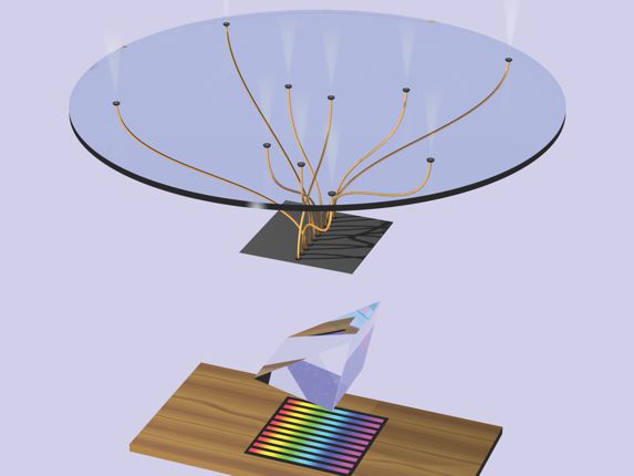
Until the 1970s astronomical telescopes were typically used just to concentrate the light from one celestial source at a time. But astronomers realized that optical fibers could be used to observe many celestial sources at once—one fiber for each source. One end of each fiber is aligned with an individual source, and the other end illuminates a spectrograph (see figure 1). Such use of fibers led to robotic technologies that could accurately align each fiber’s input to a distinct celestial object at the telescope’s focal plane.

Figure 1. Spectra of many stars or galaxies can be obtained simultaneously in a single field of view by aligning the entrance apertures of optical fibers with the images of individual sources in a telescope’s focal plane. The fibers’ downstream ends line up along an aperture in a mask that defines the entrance slit for the spectrographic grating (represented here by a prism) that creates separate parallel spectra for the different sources. (Courtesy of A. McGrath.)
Since the 1990s multifiber spectrographs have had a spectacular impact on stellar astronomy and cosmology by providing detailed spectra of more than a million stars and galaxies. 1 More recently, individual fibers are being replaced by closely packed fiber bundles with the aim of obtaining spatially resolved spectral information across the face of each galaxy in a survey of more than 10 000 galaxies. 2
But photonics has far more to offer than simply transporting light from the focal plane to an analyzing instrument. The impending generation of ELTs will employ arrays of mirrors with combined collecting surfaces up to 40 m in diameter. To create each new generation of telescopes, astronomers have had to embrace increasingly complex optical-design solutions. The ELTs, for example, will use adaptive optics to neutralize atmospheric turbulence by monitoring artificial stars created in the upper atmosphere by laser beams.
Consider the prospect of focusing the radiation collected by an ELT onto an aperture much smaller than the cross section of a human hair. If astronomers stick to conventional designs, the imaging and spectrographic instruments on those telescopes will have to become much bigger and more complex, with correspondingly higher costs and risks. Photonics offers the prospect of a new generation of instruments that are more compact and less complex, and therefore much cheaper, than conventional instruments made up of very large optical elements.
Enter astrophotonics
Astrophotonics is a burgeoning field at the interface of astronomy and photonics. It emerged in about 2001 as astronomers began thinking about the next generation of telescopes in connection with new developments in noise suppression, integral-field spectroscopy, stellar interferometry, and adaptive optics. 3
We concentrate here on the development of a new generation of spectroscopic instruments that exploit the “photonic lantern,” an astrophotonic device that allows single-mode action in a multimode fiber
4
(see box
An early successful application of astrophotonics has been to suppress unwanted noise sources in astronomical observations. When we look up at the night sky, we see stars, planets, and galaxies set against a dark background. But an infrared observer sensitive to wavelengths from 800 to 1800 nm is not so fortunate. The IR sky is overwhelmed by hundreds of very bright, narrow emission lines arising from excited OH radicals in Earth’s upper atmosphere. A long-standing goal of astronomy has been to achieve a dark IR sky by filtering out the unwanted local background. The only viable means at present for achieving the requisite complex filtering is based on fiber Bragg grating (FBG) technology.
The principle of the FBG is that light propagating along an optical fiber can be made to undergo reflection at many refractive-index increments printed onto the fiber’s core (see figure 2a). The refractive-index modulation describes a grating, and light can be made to reflect back along the full length of that grating.

Figure 2. Photonic filtering of atmospheric noise in night-sky IR spectra. (a) When the unfiltered light (red) enters a fiber Bragg grating (FBG) with a periodic refractive-index modulation Δn printed along its core, some light (blue) is reflected backward, and interference between the forward and reflected light can filter out IR emission from excited OH radicals in the atmosphere. (Courtesy of C. Trinh.) (b) Because that interference requires single-mode fibers, a photonic lantern (see box 2) feeds the telescope’s original multimode output into an array of single-mode inputs for the OH-noise filter. (c) High-resolution removal of 104 noise lines at wavelengths below 1.7 µm by an FBG filter instrument called GNOSIS on the Anglo-Australian Telescope. The night-sky IR spectrum is shown red after filtering, and blue before.
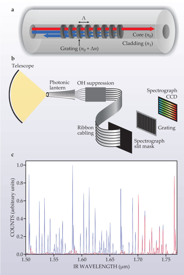
The grating is defined by the modulation period and amplitude and by a complex phase. The filtering observed in transmission arises from interference between the forward-propagating and backward-reflected light fields. The coherent addition of those light fields requires a single-mode fiber so that propagation vectors are aligned with the fiber axis. In a multimode fiber, each mode experiences the grating along a different wavevector, which leads to a spectral smearing out of the grating’s response. The solution is to use a photonic lantern to convert light from the multimode fiber into a parallel array of single-mode fibers with identical FBGs. (See box
A prototype instrument called GNOSIS at the 4-meter Anglo-Australian Telescope in New South Wales uses an array of extremely complex optical filters to suppress hundreds of OH lines. 6 As shown in figure 2b, a photonic lantern feeds light to many identical FBGs that constitute the OH filter. The IR light thus “cleaned” is fed into a spectrograph while the obscuring OH emission is reflected back to the sky. A recent demonstration of sky suppression with the GNOSIS instrument is shown in figure 2c.
That approach will soon revolutionize the way astronomers carry out IR spectroscopy. But the present implementation of photonic-lantern technology is still too elaborate for mass production. An alternative approach, for now, is to use multicore-fiber technology, which packs many single-mode cores close together along the fiber’s length. The first attempts at printing identical Bragg gratings across all the cores of a multicore fiber look encouraging. 7
In future photonic instruments based entirely on two-dimensional waveguides, a different approach will be needed. One promising technology is the micro-ring resonator used in telecommunication devices for adding or dropping discrete wavelengths. If a ring-shaped light-guiding track is placed close to a linear track, light in the latter couples to the ring if its wavelength λ satisfies mλ = 2πrn0, where r is the ring’s radius, n0 is its effective refractive index, and m is a positive integer. Such wavelengths are essentially removed from the linear track.
Microspectrographs
The workhorse instrument at most frontline astronomical observatories is the spectrograph. For a given spectroscopic resolution of instruments that are not diffraction limited, the size of such an instrument scales with the slit width, which in turn scales with the diameter of the telescope mirror. Conventional modern spectrographs can be up to 6 m long, and the ELTs will require even longer ones.
The photonic integrated-multimode microspectrograph (PIMMS) is another breakthrough application made possible by the photonic lantern. The PIMMS sidesteps the need for the huge optical instruments that have come to dominate modern astronomy. A PIMMS instrument is the size of a shoe box. One size fits all! To see why, it is important to understand how existing astronomical spectrographs work.
For a point source, an ideal telescope mirror produces a diffraction-limited image whose spread roughly equals λF, where F is the ratio of the telescope’s focal length to the diameter of its aperture. At a fixed λ, the image’s light can, in principle, be coupled into a single-mode fiber. But in practice, that coupling is not very efficient, because the diffraction pattern is not optimally matched to the fiber mode (
An important property of diffraction-limited imaging, for a given F, is that the point spread function (PSF) of a point source is independent of the size of the telescope’s aperture. For a telescope with, say, F = 15, the PSF is only 10 μm wide at visible wavelengths, regardless of aperture. That’s an order of magnitude smaller than what most telescopes actually achieve, which means that the entrance slit of a spectrograph, along with the entire instrument, could be scaled down by an order of magnitude.
In practice, many things work against diffraction-limited imaging. The PSF is distorted by atmospheric turbulence, wind shake, support structures, central mirror holes, and so on. Such distortions affect not only angular resolution but also brightness in the focal plane. So a spectrograph’s entrance slit, and the entire instrument, has to be wide enough to accommodate the blurred image.
The quest for diffraction-limited performance at a mountaintop observatory requires the use of complex and expensive adaptive optics. Nowadays the best AO systems get within 80–90% of the diffraction-limited image size at far-IR wavelengths longer than 1800 nm, but they don’t do nearly as well in the optical or near-IR.
Is there any way to retain the extreme compactness of a diffraction-limited spectrograph while accepting light from a distorted optical beam? Once again, an answer lies in the remarkable properties of the photonic lantern. The lantern’s multimode input can accept light from the distorted telescope focus, which can be regarded as a multimode structure, and convert it into an array of single-mode outputs. Since the light from a single-mode fiber, by definition, provides a diffraction-limited source, the single-mode outputs can be lined up into a slit arrangement and fed to a diffraction-limited spectrograph (see figure 2b).
The spectrograph can thus be in its most compact form, regardless of the properties of the input aperture. So we can speak of a diffraction-limited instrument, irrespective of the telescope’s perfor-mance. That’s the secret to achieving inexpensive compact instruments on the next generation of ELTs, planet rovers, and space telescopes.
Microspectrographs have extraordinary potential. A diffraction-limited spectrograph’s resolving power R ≡ λ/δλ is given roughly by mN, where m is the order of interference and N is the interference grating’s finesse—its periodic spacing divided by its line thickness. N is roughly equal to the number of combining beams produced in the spectrograph. A well-optimized, diffraction-limited spectrograph can be made very small indeed. A grating with 2000 lines per millimeter illuminated over a length of 10 mm can achieve an R of 20 000 in first order. The entire instrument need only be 10 cm long. That’s far removed from the meter-scale monolithic instruments normally built to achieve such resolution on frontline telescopes.
It all sounds too good to be true, and it is. In a conventional fiber spectrograph, a single large-aperture fiber carries the light from the telescope’s focal plane to the instrument. To achieve the same system throughput, a photonic lantern would divide the multimode input into p single-mode fibers, and all of those must be fed to the microspectrograph. For a multimode input fiber with a core diameter of 100 µm, the lantern converts the input into about 100 outputs. That requires an effective slit aperture whose length (perpendicular to the grating’s dispersion direction) is 10 times as wide as the original multimode fiber. Thus the microspectrograph needs a detector that is 10 times as long in the slit direction as a conventional instrument. The requisite increase in the number of pixels comes at a cost in money and noise; modern detectors carry a significant noise penalty in each pixel.
On the other hand, the separate spectra produced by the multiple single-mode outputs can be summed without loss of information. We can take advantage of that fact by developing detectors with thin rectangular pixels. If the long axis of each pixel is aligned with the slit direction, the light from many single-mode outputs falls onto a single pixel in each wavelength bin of the dispersed celestial light. So there’s no added noise relative to a conventional spectrograph. Detectors of that design are currently under development.
Having to deal with hundreds of single-mode fibers would seem to add unacceptably to a spectrograph’s complexity. But Robert Thomson at Heriot-Watt University in Edinburgh has elegantly addressed that problem with a device called a solid lantern. By means of ultrafast laser injection, he can scribe a hundred single-mode tracks within a small block of glass. Each track terminates along a locus defining the entrance slit to the microspectrograph. 8
Standing waves
A number of groups worldwide are pursuing remarkable variants on photonic microspectrographs that will make even stronger demands on future detectors. The fully integrated photonic spectrograph shown in figure 3a uses a special kind of spectral disperser called an array waveguide grating. Invented in 1991 by Meint Smit at Eindhoven University of Technology in the Netherlands, the grating is etched out of a 2D silicon substrate. In its simplest configuration, sketched in figure 3b, light from a single-mode fiber is fed into the bulk material, and the diverging beam illuminates a nested array of curved waveguide tracks. Each track is longer than its inner neighbor by exactly δ = mλ0/2, where λ0 is some central wavelength and m is the spectral order of interference. The output from the waveguide array then interferes at the end face to form a spectrum.

Figure 3. The fully integrated photonic spectrograph shown in (a) (Courtesy of J. Lawrence, Macquarie University) uses the array waveguide grating schematically shown in (b). Multichrome light from a single-mode fiber enters a phased array of etched tracks differing in length by a fixed small increment such that interference at the downstream waveguide produces spectral separation. (Courtesy of A. McGrath.)
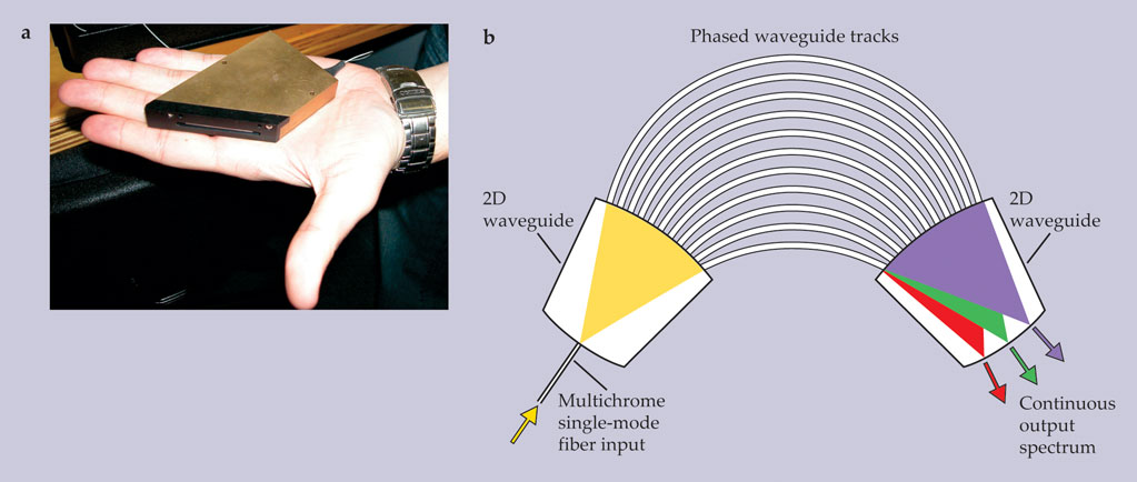
For astronomy, such an integrated photonic spectrograph has been shown to operate very close to the R = mN diffraction limit. 9 In addition to excellent light throughput of 60%, the array waveguide has another remarkable characteristic. Instead of using gratings at large incidence angles that result in lost light, it can achieve high spectral orders simply by increasing the length increment δ between adjacent tracks. Higher-order spectra are attractive because they provide greater spacing between spectral lines.
By attaching a photonic lantern to the front face of an array waveguide, one can disperse the light from a multimode fiber. But to avoid overlapping spectra in the plane of the waveguide, the output light must be dispersed in a direction perpendicular to the plane. That elegant design has recently yielded high-resolution spectra of nearby stars. 10
Another photonic spectrometer that uses a very different form of dispersion and detection is the stationary-wave integrated Fourier-transform spectrometer (SWIFTS). 11 In a SWIFTS instrument, the spectral information is extracted from the Fourier transform of a stationary interference pattern produced by two counter-propagating waves inside a single-mode waveguide. One obtains the spectrum of the incident light much as in a Fourier- transform spectrometer. The detection of the standing-wave pattern is achieved by probing its evanescent fringe field just outside the waveguide with a linear array of scattering nanodetectors, as shown in figure 4. With each detector picking up a tiny amount of the guided light, one can extract the interference signal along the entire length of the waveguide.

Figure 4. Stationary-wave integrated Fourier-transform spectrometers (SWIFTS) extract spectral information about incident light through a tightly spaced array of nanodetectors that sample the evanescent fringe field just outside a waveguide in which the light creates a standing wave. The standing wave, resulting from interference of the light with a counterpropagating version of itself, can be created in two different modes. In the Lippmann mode (a), a mirror at the waveguide’s far end reflects light back through the guide. In that case, the principal interference fringe is locked to the mirror. In the Gabor mode (b), the incident light is split into two beams before being introduced into opposite ends of the waveguide. In that case, the precise position of the principal interference fringe near the center provides additional phase information.
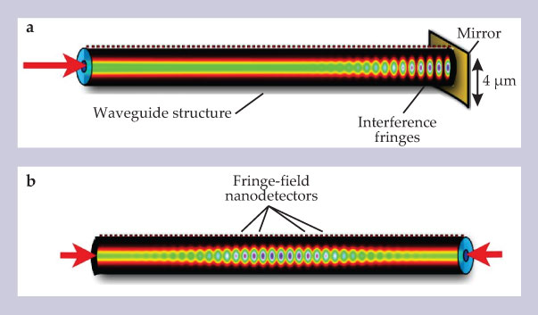
Two modes of SWIFTS operation have been proposed. They’re named after Gabriel Lippmann and Dennis Gabor, two great optical scientists of the past. In the SWIFTS–Lippmann mode, shown in figure 4a, the standing wave is produced by reflecting the injected light with a mirror at the waveguide’s far end. The principal interference (black) fringe is locked onto the mirror. In the alternative SWIFTS–Gabor mode, seen in figure 4b, the incoming light is split into two equal parts and injected into the waveguide’s opposite ends. Both modes yield the spectrum of the incident radiation. But the Gabor mode also yields phase information through the displacement of the principal interference fringe from the precise center. A device based on the Gabor mode can therefore serve as a beam combiner for the light from two remote telescopes.
The length L between the first and last detector pixel of a SWIFTS gives the spectral resolution of the device. The resolution R is roughly 2n0L/λ, where n0 is the refractive index of the propagating material. A 5-cm-long device, for example, provides a resolution of 105 at IR wavelengths near 1.5 μm. However, nanoscale detectors are not yet available to achieve the requisite sampling of fringe patterns with submicron periods; pixel sizes of standard detectors are 10 μm or bigger, which limits the instrument’s bandwidth to 10 nm. That limitation can be overcome in practice by introducing the incident light into a number of parallel SWIFTS channels, in each of which the fringe pattern is dephased by a different small phase shift.
Applications in space
At about the same time that astrophotonics was born, the field of space photonics emerged, driven by developments in laser communications. An increasing number of spacecraft require data-gathering capabilities that far exceed the capacity of microwave communication. Recent satellite demonstrations by NASA and the European Space Agency demonstrate the viability of space lasers for data communication. The use of photonics in space instruments is as yet limited, but it’s likely to grow significantly in the years ahead. 12
But there are challenges. Though the space environment itself is extremely stable, instrument designers must contend with strong shaking at the launch stage, extreme temperatures, high radiation levels, and vacuum conditions. John Mather, who led the pioneering Cosmic Background Explorer experiment, has pointed out that Cherenkov radiation due to the passage of relativistic charged particles through a couple of optical fibers aboard the satellite almost killed the experiment. But radiation-hardened materials can be used very effectively in space applications, and Cherenkov radiation can yield valuable data.
Next year the University of Sydney will launch a PIMMS-style microspectrograph, weighing only 100 grams, aboard a satellite weighing about 1 kg. It’s the first in a series of fully photonic instruments to be launched in the next few years. One of those instruments will be a fiber-based radiation counter, a large-aperture fiber coil with both ends feeding a common detector to record Cherenkov flashes along the fiber length.
One of the most innovative uses of photonics is in the ChemCam instrument aboard the Curiosity rover, now on its way to Mars. Developed by US and French scientists, the instrument will use a pulsed laser to vaporize rock surfaces. An on-board multifiber spectrograph will capture light traversing the vapor to study its composition. And soils sampled with a mechanical digger will be analyzed in a photonic waveguide that avails itself of microfluidic transport of soil particulates. A SWIFTS microspectrograph is being considered for the next generation of Mars rovers.
To date, photonics has been used for light transport, filtering, noise suppression, interferometry, and making artificial guide stars. But there are many photonic functions yet to be explored. Most of them will doubtless be restricted to optical and near-IR wavelengths, but there are signs that photonic materials will find powerful applications in the UV and mid-IR. 13 We envisage a time when whole instruments are embedded in a bulk medium or on a substrate. The first steps in that evolution have already been taken. But a major obstacle at present is the size and shape of pixels on conventional CCD detector arrays.
Applications of photonics proposed for future space missions include laser measurement of the distances between satellites flying in formation, laser communications for interplanetary missions, signal processing, and adaptive beam forming. We also foresee major advances in frequency metrology with laser frequency combs integrated into compact optical circuits. 14
Looking further into the future, we anticipate a dramatic demonstration of the power of photonics from the realization of Victor Veselago’s 1967 theory of negative-refractive-index materials (see the article by John Pendry and David Smith in PHYSICS TODAY, June 2004, page 37 ). It may even be possible to beat the diffraction limit of optical systems in some instances. But such an achievement in a bulk material will require revolutionary breakthroughs in the fabrication of metamaterials.
Many of the advances to date have built on technologies that emerged from industrial or military research. If astrophotonics and space photonics are to continue to advance, ongoing investment from the industrial sector will be important. That seems likely because many photonic developments have important applications in other applied fields—in particular, medical science and remote sensing.
Box 1. Single- and multimode optical fibers
Optical step-index fibers are characterized by a core with refractive index n0 slightly higher than n1, the index of the cladding material. The acceptance half-angle θ for light entering the fiber’s front face in air is given by
sin θ = √(n02 − n12).
Sin θ is called the fiber’s numerical aperture NA. Only light arriving within the NA cone will be transmitted along the fiber. For the fibers considered in this article, n0 − n1 is much less than unity; we call them weakly guiding fibers. The number p of different modes along the fiber for a given wavelength λ in the core material is V2/4. The dimensionless parameter V equals koa NA, where ko is the wavenumber 2π/λ and a is the core’s radius. (There are twice as many modes if we consider the polarization states.)
The number of modes for an optical system at a given wavelength is proportional to the product of the beam’s spread in cross section and angle. As shown in the figure, each mode is characterized by the indices l,m of the Laguerre polynomial Llm that describes its transverse profile. Fibers with a V less than 2.4 are single-mode in the sense that they support only the fundamental propagation mode L01. With increasing l, modes exhibit more azimuthal nodes; increasing m shows more concentric nodes.
A crucial distinction between multimode and single-mode fibers is that the different modes of the former have different optical paths in the fiber, which gives rise to a “modal dispersion” that greatly complicates any attempt to treat the light with a photonic device such as a fiber grating. But that problem has been solved by the introduction of the photonic lantern (

Box 2. Photonic lantern
One of the most remarkable devices to emerge from astrophotonics is the photonic lantern, whose purpose is to efficiently couple light between a multimode fiber and a parallel array of single-mode fibers.4 Because different modes of a light beam propagating along a multimode fiber traverse different pathlengths, spectral lines become progressively smeared out as the light propagates. This modal dispersion is distinct from ordinary material dispersion.
Any spectrographic grating requires that an incident wavefront interfere coherently across the grating. If, for example, the grating is placed in a strongly converging beam, constructive interference breaks down due to loss of that coherence. A related phenomenon occurs when one tries to print a fiber Bragg grating (figure 2a) into a multimode fiber. A sinusoidal refractive-index modulation about the unmodulated index n0 with a period Λ printed along the core has the strongest response to photons at a specific wavelength λB = 2n0Λ propagating along the core’s axis. But light propagating in some off-axis direction experiences a different modulation pattern. In essence, the response of the grating becomes smeared out over a broad band of wavelengths. The same is true of any photonic function printed into a multimode fiber. And that’s been the main stumbling block in the way to wider application of photonics.

S. LEON-SAVAL
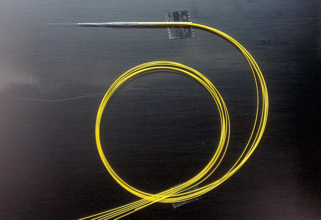
How can single-mode photonics be done with multimode-fiber input? Ideally, one wants to separate out the p different propagating spatial modes into p single-mode channels and ensure that all wavelengths in a broad spectral band can be treated alike. The solution is elegant: The light is made to pass from the multimode fiber through a long gentle taper down to an array bundle of as many single-mode fibers as there are modes in the multimode fiber. The photo shows the taper transition from a 50-µm-diameter multimode core to seven single-mode outputs. The lantern technology has been shown to work efficiently for up to 61 modes. 15
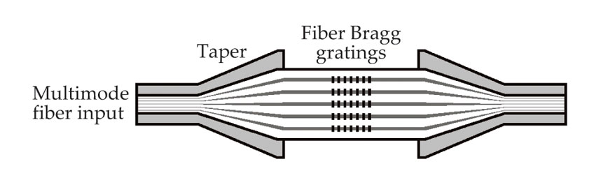
The multimode fiber’s light couples into all the single-mode fibers. The energy transfer is very efficient, and it’s reversible if the number of degrees of freedom is conserved along the length of the lantern. One can fabricate identical Bragg gratings into each of the single-mode fibers. Some applications require that grating outputs be fed back into a second multimode fiber in order to make use of existing spectrographs optimized for multimode input. That’s easily achieved by adding a second photonic lantern in reverse, as shown in the sketch.

UNIVERSITY OF BATH
References
1. M. Colless et al., Mon. Not. R. Astron. Soc. 328, 1039 (2001); https://doi.org/10.1046/j.1365-8711.2001.04902.x
D. J. Eisenstein et al., Astrophys. J. 633, 560 (2005). https://doi.org/10.1086/4665122. S. M. Croom et al., Mon. Not. R. Astron. Soc. 421, 872 (2012).
3. J. Bland-Hawthorn, P. Kern, Opt. Express 17, 1880 (2009). https://doi.org/10.1364/OE.17.001880
4. S. G. Leon-Saval et al., Opt. Lett. 30, 2545 (2005). https://doi.org/10.1364/OL.30.002545
5. J. Bland-Hawthorn et al., Proc. SPIE 7735, 773541 (2010).
6. S. C. Ellis et al., Proc. SPIE 7735, 773516 (2010).
7. T. Birks et al., “Fibers are looking up,” paper pre-sented at Frontiers in Optics, 24 October 2010. Available at http://www.opticsinfobase.org/abstract.cfm?URI=FiO-2010-FTuU1 .
8. R. R. Thomson et al., Opt. Express 19, 5698 (2011). https://doi.org/10.1364/OE.19.005698
9. N. Cvetojevic et al. et al., Opt. Express 17, 18643 (2009). https://doi.org/10.1364/OE.17.018643
10. N. Cvetojevic et al., Opt. Express 20, 2062 (2012). https://doi.org/10.1364/OE.20.002062
11. E. le Coarer et al., Nat. Photon. 1, 473 (2007). https://doi.org/10.1038/nphoton.2007.138
12. D. E. Smith et al., Science 311, 53 (2006). https://doi.org/10.1126/science.1120091
13. S. E. Tuttle et al., Proc. SPIE 7732, 773227 (2010);
B. J. Eggleton, B. Luther-Davies, K. Richardson, Nat. Photon. 5, 141 (2011).14. T. Steinmetz et al., Science 321, 1335 (2008); https://doi.org/10.1126/science.1161030
M. T. Murphy et al., Mon. Not. R. Astron. Soc. (in press), doi:10.1111/j.1365-2966.2012.20656.x.15. D. Noordegraaf et al., Opt. Express 18, 4673 (2010).https://doi.org/10.1364/OE.18.004673
More about the authors
Joss Bland-Hawthorn is a professor of physics and federation fellow at the University of Sydney in Australia. Pierre Kern is a research engineer in the Institute of Planetology and Astrophysics of CNRS and Joseph Fourier University in Grenoble, France.


