The Hall effect and rocket flight
DOI: 10.1063/1.3120905
Chemical rockets take the random thermal motion of a hot gas generated by combustion and convert it into directed velocity. The maximum speed that can be obtained—usually a few kilometers per second—is limited by the temperature generated by the released chemical energy, typically about 2500 °C. In contrast, plasma rockets, also called plasma thrusters, derive their energy from electricity and expel ions at a velocity that can easily exceed 10 times that of their chemical counterparts. The thrust delivered by the rocket to the spacecraft is equal to the rate of mass discharged from the rocket multiplied by the exhaust velocity. Plasma rockets produce more thrust for a given rate of mass ejection and, hence, transfer more momentum. The plasma advantage is somewhat mitigated by the need to have on-board equipment to generate the electric power. Nonetheless, there has been a dramatic increase in the use of plasma thrusters for orbit maintenance in geosynchronous telecommunications satellites.
The prospects for plasma propulsion in more demanding unmanned and manned interplanetary flight depend on the availability of electric power and on the ability of the thruster to operate for tens of thousands of hours. Traditional plasma rockets, known as ion thrusters, employ high-voltage grids to produce a strong electric field used to extract and accelerate ions to high velocities. Those ions hit and degrade the grids, limiting the thruster’s life. One variant of a modern plasma thruster uses magnetic fields and the Hall effect to generate thrust without extraction grids. The gridless plasma thruster holds promise for longer missions; however, shaping the magnetic field to produce the directed ions and achieve the desired performance will require a deep understanding of the underlying plasma physics.
When electrons move in circles
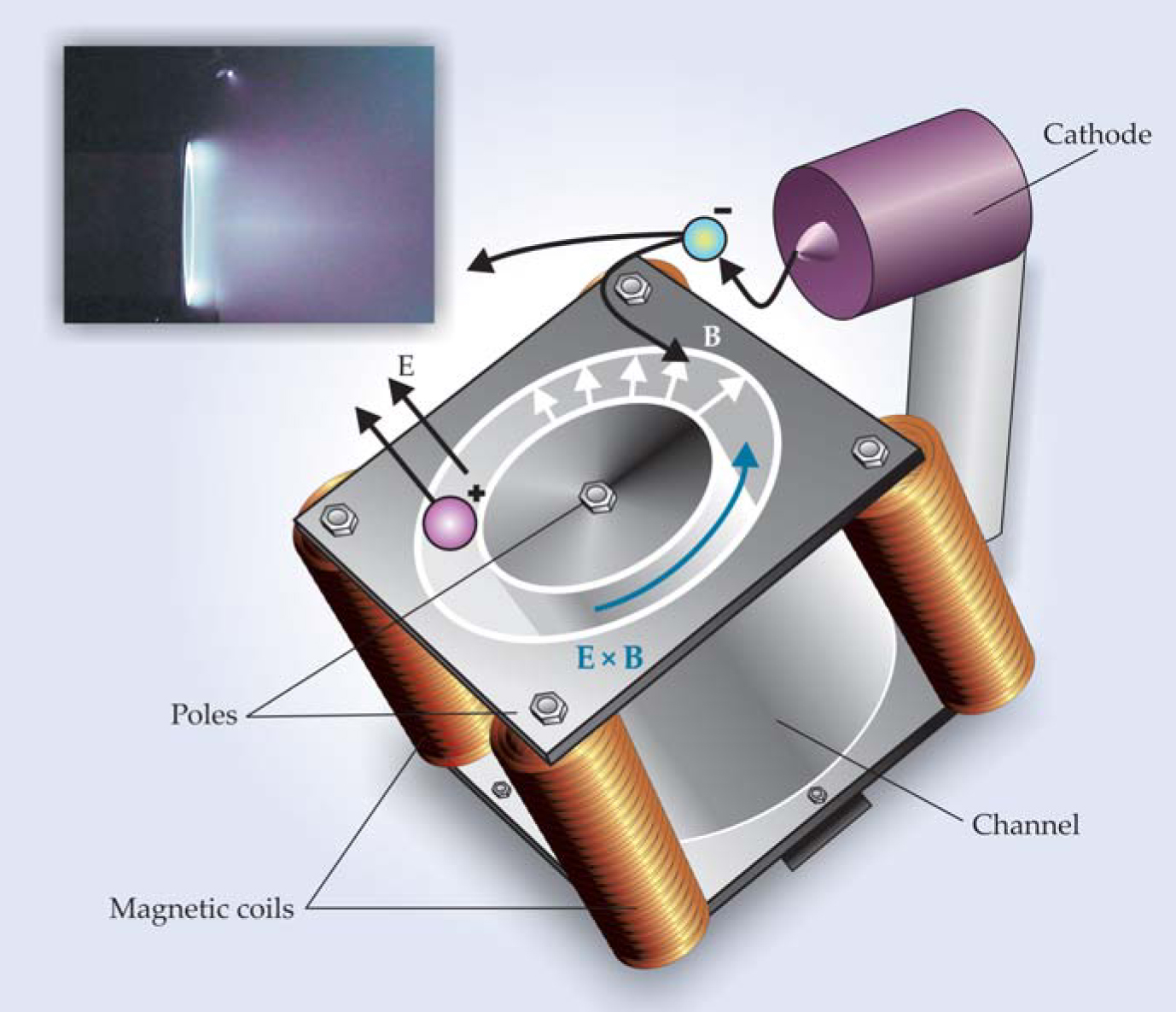
The Hall effect thruster (HET) relies on the deflection and trapping of gaseous electrons in the presence of a strong magnetic field. The simplest expression of the Hall effect, as originally discovered in semiconductors, arises when electrons and the positively charged holes they leave behind migrate in response to an electric field E and a perpendicularly applied magnetic field B. The charged particles initially accelerate parallel to E, but as they pick up speed, the magnetic field deflects them, at first in a direction perpendicular to E and always perpendicular to B. If the electric and magnetic fields occupy enough space, electrons and ions will eventually execute helical motion and drift along the E × B direction—a phenomenon known as E × B drift. However, as illustrated in the figure, in an HET, the magnetic field is confined to a cylindrically symmetric region; moreover, the field is concentrated in a region whose width is just a few times the electron’s gyromagnetic radius. The ions, typically singly charged xenon, are much heavier than electrons and accelerate through the magnetic field before it can bend them into helical trajectories. The result is a net electron Hall current in the E × B direction due to the magnetically trapped electrons. The ions continue in the direction of E and escape from the HET; it is the escaping ions that provide the thrust.
The recoil force on the spacecraft is communicated through the mutual induction between the Hall current and the current in the electromagnets that generate the magnetic field. Thus a healthy Hall current is critical if the spacecraft is to be accelerated to high velocities. To keep the Hall current unobstructed, engineers arrange the electric discharge to take place in an annular configuration. The ion-forming propellant is introduced through the anode. It then encounters a fraction of the electrons emitted by the cathode and becomes ionized. The electrons stripped from the propellant produce further ionization, and the resulting “avalanche” process eventually produces a substantial Hall current.
Absent collisions, essentially all the electrons would be deflected into the E × B direction. That azimuthal motion is desirable, as it allows for greater thrust to be generated by expelled ions. Nonetheless, some anode-directed electron current is necessary to complete the electric circuit. To achieve that current component, engineers control the electron-scattering rate and partially disrupt the helical trajectories by increasing the flow of propellant and hence the collision frequency v c at which the electron will strike a neutral molecule. In addition, reducing the magnetic field leads to greater anode-directed electron current, because it increases the electron’s gyromagnetic radius and reduces the gyromagnetic frequency ωg (ωg = qB/m, where q and m are the charge and mass of the electron, respectively). The ratio ωg/v c is the so-called Hall parameter—a measure of the magnetic trapping of the electrons. The smaller the Hall parameter, the greater the anode-directed electron current and the lower the thrust. Much research in the development of modern Hall thrusters involves understanding the physics controlling the Hall parameter.

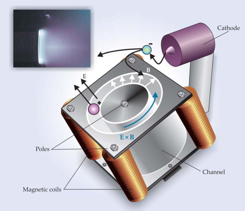
In the typical Hall effect thruster (HET) sketched here, a portion of the electrons emitted from a cathode migrate into a coaxial channel with a ceramic lining. The anode (not shown) is at the base of the channel. The electrons become trapped by a strong radially directed magnetic field B and drift in the azimuthal (E × B) direction, perpendicular to both the electric (E) and magnetic fields; positive ions escape from the channel and impart thrust. The inset shows a Hall thruster in ground testing. Note the glowing plasma at the mouth of the coaxial channel and, as a small white dot, at the cathode. The nature of the plume to the right of the mouth is a subject of current research.

You might ask, What more is there to understand? After all, for a given propellant flow, isn’t the Hall parameter simply controlled by the magnetic field? In part, the answer is yes; however, when a current is driven through a plasma in an imposed magnetic field, the plasma becomes unstable and fluctuations evolve into weakly correlated turbulence. Understanding the evolution of turbulence in magnetized plasmas and the impact of turbulence on the containment of hot plasma has plagued fusion physicists for decades (see the article by Don Batchelor, (Physics Today, February 2005, page 35
Several measurements taken at Stanford University’s plasma physics laboratory have shown that the effective Hall parameter correlates well with the degree of turbulence in the plasma. Meanwhile, the ultimate goal of Hall thruster theory and simulations is to accurately predict the electron conductivity through direct simulations of the turbulent nature of the plasma or through models of how time-averaged properties establish or tame turbulence. The local electron conductivity, as determined by the magnetic field and the ensuing turbulence, establishes the local electric field. If engineers could accurately predict that conductivity, they could better shape the magnetic fields—and therefore electric fields too—to obtain a better understanding of how performance is related to thruster configurations and to predict and maximize the overall life expectancy of the engine.
Gridless does not mean no erosion
In a common HET variant, ceramic walls line the annular channel and protect the iron poles from the energetic plasma ions. If the magnetic field is to be strong enough to confine the electrons, the channel can only be of limited width. That channel requirement, in turn, determines an upper limit on the allowable thickness of the ceramic walls. In practice, the wall thickness in a 1-kW HET is typically 3 mm. Accelerated ions with a radial component are destined to strike the ceramic walls of the channel near the exit and can degrade and erode those walls. Once the walls erode through the ceramic to expose the iron pole, the end is near for the thruster, since iron degrades much more quickly than the protective ceramic; the recession of the pole will lead to a decrease in the strength of the magnetic field. In a 1-kW HET with a typical outer diameter of 0.1 m, the xenon ions carry about 2 A of current. If a mere 1 in 10 000 of them strike a 3-mm thick wall of boron nitride within 3 mm of the end of the channel, the wall protecting the magnetic pole will erode once 200 kg or so of xenon have been processed.
A 1-kW HET that processes 200 kg of xenon propellant can deliver a relatively small spacecraft to the Moon. Indeed, the European Space Agency’s 370-kg Smart-1 spacecraft flew to the Moon in 2003-04 with a 10-cm-diameter Hall thruster processing 80 kg of xenon (see http://www.esa.int/SPECIALS/SMART-1/index.html
Those of us who work with HETs enjoy the mix of engineering, plasma physics, and materials science. There’s a real excitement in progressing toward solutions that will be applied to spaceflight while also attacking problems that may be relevant to a range of related technologies such as fusion energy production.
References
1. N. B. Meezan, W. A. Hargus Jr, M. A. Cappelli,“Anomalous Electron Mobility in a Coaxial Hall Discharge Plasma,” Phys. Rev. E 63, 026410 (2001).https://doi.org/10.1103/PhysRevE.63.026410
2. C. A. Thomas, N. Gascon, M. A. Cappelli,“Nonintrusive Characterization of the Azimuthal Drift Current in a Coaxial E × B Discharge Plasma,” Phys. Rev. E 74, 056402 (2006).https://doi.org/10.1103/PhysRevE.74.056402
3. D. M. Goebel, I. Katz, Fundamentals of Electric Propulsion: Ion and Hall Thrusters, Wiley, Hoboken, NJ (2008).https://doi.org/10.1002/9780470436448
4. E. Y. Choueiri,“New Dawn for Electric Rockets,” Sci. Am., February 2009, p. 58.https://doi.org/10.1038/scientificamerican0209-58
More about the authors
Mark Cappelli is a professor in the school of engineering at Stanford University in Stanford, California.
Mark Cappelli, Stanford University, Stanford, California, US .


