The customized reflections of freeform mirrors
DOI: 10.1063/1.3502558
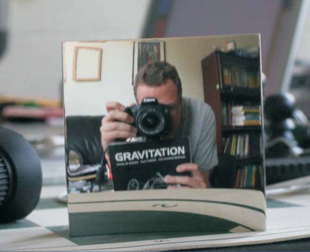
Reflective objects such as plumbing fixtures, electronics, automobile parts, and travel mugs all offer a strange representation of the world. The mirror in figure 1 offers a view that is strange in its own way. The surfaces of all these objects are not often built to function as optical components, and they generally lack the rotational symmetry possessed by optical devices. The irregular surfaces are called freeform.

Figure 1. What’s wrong with this picture? The image in the saddle-shaped mirror shows the author holding the classic textbook Gravitation, by Charles Misner, Kip Thorne, and John Wheeler. The title of the book appears normal. Objects near the edges of the mirror, however, are distorted; it is not possible to construct a perfect, nonreversing mirror.
The ability to machine freeform surfaces of optical quality has been available for only about a decade, and is largely due to the Defense Advanced Research Projects Agency conformal optics program. The relative complexity of freeform surfaces means that designing a surface for a particular end is trickier than for rotationally symmetric optical elements, and traditional design approaches can be problematic. New design techniques, however, have emerged in concert with the improved machining capability, as have applications for optical systems containing freeform surfaces. In this Quick Study, I address a basic problem for a single mirror: How can one design a mirrored surface to realize a specific distortion? (More sophisticated materials, too, can achieve specific distortions. See the article on
Pinholes and perspective
Before we turn to a more precise formulation of the problem, let’s consider a simple model of image formation. A good approximation for most cameras and the human eye is the pin-hole camera. The ideal device allows light to enter through a single point that will be taken as the coordinate origin in the upcoming mathematical analysis. The light entering the camera comes from an external object, which may be viewed as the source of a collection of rays. For the ideal pinhole camera, at most one ray emanating from a point on the object can enter the pinhole; the image recorded by the camera is the collection of points where the entering rays hit an image plane, usually some electronic sensor or film. In reality, the pinhole has a nonzero diameter, and a small cone of rays enters the camera from each point on an object.
The pinhole camera forms a so-called perspective projection, first brought into prominence during the Renaissance. The artists of that time found that the projection allowed for a more natural representation of the three-dimensional world on a two-dimensional plane than in the style of the Middle Ages. For an image plane located at x = −1, perspective projection takes the object point (x, y, z) and maps it to the point (−1, −y/x, −z/x). The mapping has many wonderful properties, one of which is that straight lines on the object project to straight lines in the image plane. If a curved reflective surface intervenes between object and pinhole, however, then a distorted image will be formed, as shown in figure 2(a).

Figure 2. Designed distortion. (a) The image produced in a pinhole camera is distorted if a curved mirror intervenes between object and hole. (b) Mirrors can be specifically designed to yield images with desired properties. This image defines the mathematical elements used in the construction described in the text.
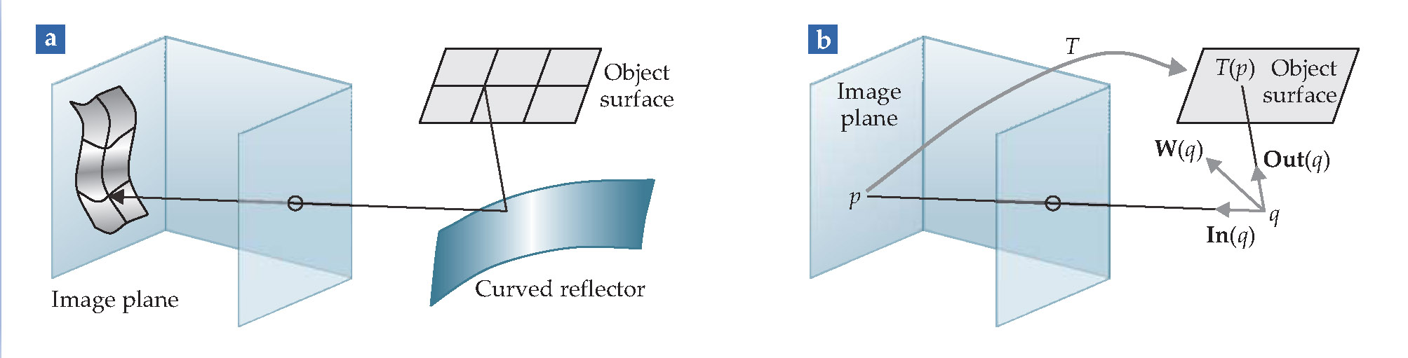
The problem that concluded the previous section can now be stated precisely: Suppose we choose a specific object surface and want to view it reflected in a mirror so that a given distortion is achieved on another specified surface—an image plane. What is the mirror that will achieve that distortion? In general, a specified distortion can be only approximately obtained and is realized by a freeform mirror.
From image to object
Thanks to the reversibility of geometric optics, we can view the image plane of a pinhole camera as a source of rays that travel out of the pinhole, reflect off the mirror, and terminate on the object surface. In that reversed view, the mirror implies a map from the image plane to the object surface. Although the object surface is often a plane, it need not be. The givens for the problem are thus an image plane, an object surface, a point pinhole, and a transformation T that maps the image plane to the object surface. The solution is a mirror surface.
The key step in solving the problem is to construct a vector field that is perpendicular to the solution surface, provided such a surface exists. Consider a point q that lies on a ray emanating from the pinhole camera, as in figure
When do surfaces perpendicular to W exist? Certainly, such surfaces can be found if there is a scalar function φ with W = ∇φ. In that case many solutions can be found—any surface of the form φ(x, y, z) = constant will do. That is a rare situation, however, realized if and only if ∇ × W = 0. A less stringent requirement is that W be a multiple of a gradient; that is, the vector field may be put in the form W = ψ∇φ. In that case, which occurs if and only if (∇ × W)· W = 0, surfaces of constant φ are again solutions. But even that case is rare. In practice, we’ll need to be content with a surface that is approximately perpendicular to W. One approach to obtaining such a surface is to find a function φ that minimizes ∫ v |∇φ × W|2 dx dy dz, where V is a volume of space within which we want to build the mirror and φ is an element of a finite-dimensional function space that does not include φ = 0. (Finite-dimensional function space means that φ may be expressed as a finite sum φ = ∑ n an · φ n of preselected “basis functions” φ n .)
To put some flesh on the formalism, let’s work out in detail an example for which the solution surface is a plane mirror located at x = a > 1. Choose both the image plane and the object plane to be located at x = 1, with the understanding that any rays hitting the image plane must continue through the pinhole located at the origin, beyond which they may encounter some registering medium at x = −1. Because we have placed the image and object planes at the same positive value of x, we won’t need to explicitly account for the inversion that happens when rays pass through the pinhole; that simplification will render more apparent the meaning of the transformation T corresponding to the plane mirror.
To obtain T, imagine that a light ray starts at the pinhole and passes through the image plane at p = (1, u, v). It continues onto the solution surface at x = a, to arrive at the point q = (a, au, av). The reflected ray intersects the object plane at T(p) = (1, [2a −1]u, [2a −1]v). Evidently—no surprise—the effect of the mirror is simply to scale the image plane.
The vector connecting p to q is (a − 1)(1, u, v), whence
Note that the only mirror that can faithfully implement the transformation T(1, u, v) = (1, [2a −1]u, [2a −1]v) is the plane mirror at x = a. If we had tried to construct a solution surface in the vicinity of any other x value, we would not be able to find an exact solution surface.
As a second example, take the object plane and the image plane to once again both be at x = 1 and define T(1, u, v) ≡ (1, −αu, αv). As with the flat mirror of the previous example, the transformation scales the image plane, but because of the relative minus sign in the y and z coordinates, the solution surface will not reverse an object as a conventional mirror does.
The relative minus sign also means, alas, that no exact solution surface exists. I obtained an approximate solution surface confined to the rectangular volume x = 34±1 cm, y = z = 0±3 cm, and constructed a prototype mirror. With α = 160, the mirror’s field of view is wide enough that I could see myself in the mirror when it was held at arm’s length, as shown in figure 1. To achieve the appropriate ray paths, the mirror is saddle-shaped.
The technique of using ray tracing to guide the construction of freeform mirrors can be applied to a variety of problems. For example, the second additional resource in the list describes how to design a driver-side mirror with no distortion or blind spot.
References
1. E. Kreifeldt, “DARPA Turns Researchers Loose on New Class of Optics,” Opt. Photonics News 8(1), 6 (1997).
2. R. A. Hicks, “Controlling a Ray Bundle with a Freeform Reflector,” Opt. Lett. 33, 1672 (2008).
More about the authors
Andy Hicks is a professor of mathematics at Drexel University in Philadelphia.
R. Andrew Hicks, Drexel University, Philadelphia, US .


