Time-reversed microwaves beat the diffraction limit
DOI: 10.1063/1.2731958
The immediate vicinity of an oscillating source is filled by an evanescent standing wave whose energy dwindles to nothing within a wavelength or so. Although its range is feeble, the evanescent wave has one advantage over its propagating counterpart: It harbors information at scales finer than the oscillation wavelength.
Getting at that closely held and often valuable information usually entails bringing a lens or probe into the evanescent wave field itself. Near-field optical microscopes meet the challenge and provide subwavelength views of cells, nanocircuits, and other tiny objects.
Mathias Fink and his team from the University of Paris VII have built a simple yet ingenious antenna that draws the evanescent wave out of the near field and into the far field. When used in combination with a device called a time-reversal mirror, the antenna overcomes the diffraction limit and focuses microwaves onto a spot 1/30 of a wavelength wide. 1
Although it can’t form images, the antenna–TRM combination could prove useful in wireless telecommunication. At around 2 gigahertz, the frequencies used by most mobile phone networks are close to the upper limit of what’s practical. Raising them further to boost bandwidth would turn buildings, trees, and other objects from helpful reflectors into signal-sapping absorbers.
The mobile phone wavelength is bigger than the phone itself. If future phones are to transmit and receive richer data, they’ll need more than one antenna. To handle two or more independent data streams, normal antennas would have to sprout from the phone like TV rabbit ears; diffraction-beating antennas would fit inside. Figure 1 shows what they could do.

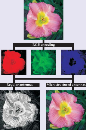
Figure 1. As a test of superresolution, the Paris researchers separated a color image into red, green, and blue components and transmitted the encoded components simultaneously from three adjacent antennas. A time-reversal mirror sent the components back toward the antennas. Because the antennas beat the diffraction limit, each antenna received only one color, despite being separated by only λ/30. Recombining the components recreated the original color image.
(Adapted from ref. 1)
Back to the source
Beating the diffraction limit in the microwave regime is the latest application of time reversal, a technique that Fink and others pioneered in acoustics in the early 1990s (see Fink’s Physics Today article, March 1997, page 34 ). Time reversal is possible in a lossless medium because the sole time derivative that appears in the wave equation is second order. Both the forward-propagating wave Ψ(r, t) and the backward-propagating wave Ψ(r, −t) represent valid solutions.
The conversion of Ψ(r, t) to Ψ(r, −t) is carried out by a time-reversal mirror, which refocuses waves back onto their source. In effect, a TRM behaves like a concave mirror, but it doesn’t reflect waves. Rather, it retransmits a time-reversed version of the incident waves.
A TRM consists of a bank of transducers connected to signal-processing equipment. Acting first as microphones, the transducers convert the incident wave into an electronic signal, which is fed into an analog-to-digital converter. The digitized signal is flipped in time and then used to drive the transducers. Acting now as loudspeakers, the transducers transmit the time-reversed wave back to its source.
Before a signal can be flipped, it must be sampled and time tagged. The earliest experiments were done with ultrasound, whose few-megahertz oscillations are relatively easy to sample. With frequencies of a few gigahertz, microwaves represent the limit of sampling technology.
In theory, a TRM needs to intercept all 4π steradians of the forward-propagating wave field to generate a faithful, backward-propagating copy. In practice, complete coverage is often unnecessary. If wavefronts bounce off walls and other obstructions on their way to the TRM, they gather enough directional information to make up for incomplete coverage. In a reverberating environment, a single transducer suffices.
When Fink began working with microwaves five years ago, he hoped time reversal would help improve wireless communication in cluttered environments. Because microwaves reflect off buildings and other surfaces, a direct line of sight from transmitter to receiver isn’t needed. Those same reflections blur reception, but when time reversed they correspond to potentially helpful reverberations that could promote focusing.
As their first step in the microwave regime, Fink and his collaborators, Julien de Rosny, Arnaud Tourin, and Geoffroy Lerosey, set out to measure how well a TRM focuses microwaves. Rather than move an antenna to map the focal spot, as they’d done in their ultrasound experiments, they opted to use an array of fixed antennas spaced λ/10 apart. The distribution of antennas that recorded a returning signal would yield the spot size.
Because a TRM sits in the far field, diffraction should limit the size of the refocusing spot to λ/2. If one antenna transmitted Ψ(r, t), then, given their spacing, at least five antennas should receive Ψ(r, −t). But when de Rosny and Lerosey ran the experiment, they found only the transmitting antenna received the reversed signal. The refocusing appeared to beat the diffraction limit to yield superresolution.
Convinced they’d seen an artifact, de Rosny and Lerosey tried to find and eliminate it. Fink, however, suspected that the superresolution arose from the presence of the other antennas. He pointed out that in a Green function analysis of the antennas, the size of a focal spot corresponds to the size of the imaginary part of the Green function. In free space, the imaginary part extends over λ/2, but when a source is surrounded by inhomogeneities—additional antennas, for example—the imaginary part is smaller.
For a year, the researchers puzzled over their experiment. Then, in March 2006, Lerosey took the Green function analysis at face value and designed and built a new antenna to test it. The antenna, illustrated in the inset of figure 2, consists of the usual metal wire surrounded by a random arrangement of passive wires that resemble dry spaghetti.

Figure 2. The key to focusing microwaves more tightly than the diffraction limit lies in surrounding an antenna with scatterers (inset). In effect, the scatterers gather subwave-length-scale information from the near field and transmit it into the far field, where it reaches the time-reversal mirror along with the propagating wave. The TRM’s eight antennas reverse the forward-propagating wave and send it back to the original antenna. That antenna’s neighbors detect little of the signal, even though they are only 1/30 of a wavelength apart.
(Adapted from ref. 1)
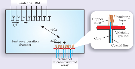
Figure 2 also shows the experimental setup. Eight antennas, each surrounded by spaghetti wires, were spaced 4 mm apart, which corresponds to λ/30. The TRM consisted of eight antennas and associated equipment. A 1-m3 box enclosed both the TRM and the antennas to provide the requisite reverberation.
The test itself consisted of comparing the result of transmitting a sharp pulse from two adjacent antennas, 3 and 4, and refocusing the time-reversed signal back onto the antennas. Panels a and b of figure 3 show the signals recorded by the TRM from antennas 3 and 4, respectively. Because of reverberation, which magnifies small path differences, the signals look different, despite the antennas’ proximity. By contrast, the refocused signals recorded by the two antennas, as shown in panels c and d, look identical and are as sharp as the forward-propagating originals.

Figure 3. Adjacent antennas, even though they are separated by λ/30, can transmit and receive microwave pulses independently. (a, b) The signals recorded by the time-reversal mirror from antennas 3 and 4 are spread out by reverberation. (c, d) When reversed and sent back to the antenna that emitted them, the pulses regain their original duration. (e) If the antennas are surrounded with scatterers, the reversed pulses return to the emitting antennas. Without the scatterers, the reversed pulses spread over neighboring antennas (dashed lines).
(Adapted from ref. 1)

The sizes of the refocused spots are shown in panel e. Even though the two antennas were just λ/30 apart, the signals returned to each antenna. Neighboring antennas receive little spillover.
Sending flowers
Despite running their experiment 100 times and obtaining the same result, the Paris researchers remained skeptical of their superresolution. To convince himself and his colleagues, Lerosey proposed a second test: Separate a color image into its red, green, and blue components. If the superresolution is real, three closely spaced antennas should be able to transmit and receive the encoded red, green, and blue images without spillover. Recombining the refocused images should yield the original image in full color. But if the superresolution is spurious, the three antennas will receive the same loosely focused signal; the image will be in black and white.
As figure 1 shows, Lerosey’s test succeeded and vindicated not only Fink’s Green function explanation but also an equivalent theoretical treatment. In 2000 Rémi Carminati of école Centrale Paris and his collaborators analyzed the time-reversal symmetry of fields containing evanescent components. 2 Using Werner Heisenberg’s S-matrix approach, they showed that scatterers placed in the near field can, in effect, convert an evanescent wave into a propagating wave.
Time reversal isn’t the only new path to superresolution. So-called metamaterials that have negative indices of refraction can bend light so strongly that an image is produced in the near field. A second lens or probe can transfer the image into the far field for readout.
Fink argues that metamaterials have an inherent drawback. In focusing beyond the diffraction limit, waves pass through the metamaterial. So far, negative refraction is achievable only for single wavelengths and in a highly anisotropic way.
Time reversal, on the other hand, achieves superresolution not through refraction but through a mathematical operation akin to reflection. What the TRM and antennas are made from doesn’t impair their focusing ability. Fink hopes soon to apply his time-reversal technique to the production of images.
References
1. G. Lerosey, J. de Rosny, A. Tourin, M. Fink, Science 315, 1120 (2007).https://doi.org/SCIEAS
2. R. Carminati, J. J. Sa´enz, J. -J. Greffet, M. Nieto-Vesperinas, Phys. Rev. A 62, 012712 (2000).https://doi.org/PLRAAN


