Spin waves control the magnetization around them
DOI: 10.1063/PT.3.4403
As electronics get faster and smaller with more densely packed elements, Joule heating from electron motion and the resulting collisions becomes more prominent. Heat limits the performance of electrical devices and requires built-in cooling methods—from fans to heat sinks. A device that transports information without moving electrons would avoid such power dissipation, and so-called magnonic devices would do just that.
In magnonics, spin waves embody and transfer information through the collective precessions of electron spins that transport angular momentum while the electrons stay put. Although related, magnonics is distinct from spintronics, which uses the electron spin as an additional degree of freedom but still relies on electron motion in the form of electrical spin currents.
The spin-wave quasiparticle, known as a magnon, flows and carries spin angular momentum in much the same way that electrons do. In a well-prepared sample, it can propagate as far as centimeters—three orders of magnitude farther than electrical spin currents—and spin waves have already performed as logic gates. 1
Despite their advantages, magnons are trickier to direct and measure than electrons are. A step toward making magnons more manageable has now been taken by two groups—one led by Luqiao Liu of MIT and the other by Hyunsoo Yang of the National University of Singapore. Their experiments have revealed how magnons both control and are controlled by their magnetic environment. The results suggest a design for all-magnon devices that are free from Joule heating and prove that magnons are capable of applications like manipulating magnetic memory.
Generating spin waves
The key for both studies was producing strong spin currents. A few techniques can generate spin waves, but they share a basic scheme: Take a material with the electron spins aligned in one direction and flip or disturb one spin state. The interaction between the flipped electron and its neighbors starts the electron spin precession and sends spin waves through the material. Techniques use different methods for disturbing the electron spins and different materials for magnon propagation.
Each group chose a different magnon-generation strategy and material system. Liu and his colleagues were interested in how spin waves respond to the interface between two magnetic domains, or a domain wall, as a possible method to manipulate the waves. 2 Because an external magnetic field could destroy the domain wall, the researchers required an alternative method to nudge the electron spins into a spin wave. They also needed a material that isn’t too magnetically damping—otherwise it will extinguish spin waves—and that is thick enough to host a strong spin-wave signal. It’s also easier to introduce spin waves in a material with strong magnetic anisotropy.
Liu and his colleagues settled on a cobalt–nickel multilayer film. In their device, the spin wave is set in motion by an embedded microwave antenna, which provides an alternating local magnetic field that induces spin precession. Microwave antennas are the classic technique for creating and detecting spin waves, and their dimensions set the resulting spin wave’s wavelength.
In the second study, Yang and his colleagues opted for a newer strategy that requires two specialized material layers: One turns an electrical signal into a strong electrical spin current, and the other efficiently transports spin waves. 3 The electrical spin current in the first layer induces spin waves in the second layer through the spin Hall effect. (See Physics Today, May 2010, page 13 .)
For the electrical spin-current layer, a topological insulator—such as Yang’s selection, bismuth selenide—is a natural choice. Although insulating in its bulk, it has surface states that are metallic and have distinct channels based on the spin. (For more on topological insulators, see Physics Today, April 2009, page 12 .) For the spin wave layer, the group selected nickel oxide, an antiferromagnetic insulator with a few crucial advantages. Insulators in general are more efficient than conductors at carrying spin waves because insulators don’t have conduction electrons bumping around and disrupting the waves. Antiferromagnets have the added benefit of hosting spin waves that are in the terahertz range, which allows data to be transmitted at high speeds.
Changing the domain wall
With their spin-wave sources selected, the groups were ready to explore how spin waves interact with magnetization. Two of Liu’s graduate students, Jiahao Han and Justin Hou, built a setup capable of simultaneous imaging in two modalities. Microwave transmission imaging tracks the amplitude and phase of the spin wave; magneto-optical Kerr effect (MOKE) imaging maps the magnetization through changes in the phase and intensity of light reflected off the sample.
Liu set up the Co–Ni films with an up magnetic region (blue box in figure
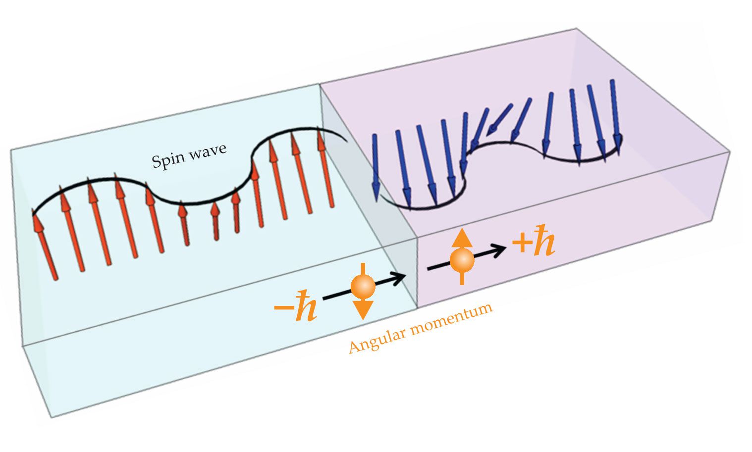
Figure 1.

Spin waves hit a magnetic domain wall (the boundary between the blue and pink boxes) in a magnetic film. As it moves from left to right, the spin wave carries spin and angular momentum (orange) and comprises the collective precession of electron spins (red and blue arrows). At the domain wall the phase and angular momentum of the spin wave flip. (Adapted from ref.
Kirschner also predicted that the domain wall would move because of conservation of angular momentum. At the wall, the magnon’s angular momentum changes by 2ℏ from spin down to spin up, and there’s no reflection. The momentum is thus transferred to the domain wall, and the torque from that spin transfer drives the wall in the opposite direction of the spin wave.
When Liu and his group mapped the magnetization, they saw the domain wall shift a few micrometers after the spin wave passed through. Other groups have observed a magnetic domain wall shift from the electron spin-transfer torque, 5 but Liu and his group are the first to see the behavior from magnon torque.
Spin waves flip the switch
Yang and his postdoc Yi Wang were initially interested in electron spin-transfer torque in Bi2Se3 and ferromagnet heterostructures as a method to switch magnetization. They investigated how the torque exerted by electrons as they flow into a magnet changes with the thickness of a NiO layer inserted below the magnet (see figure
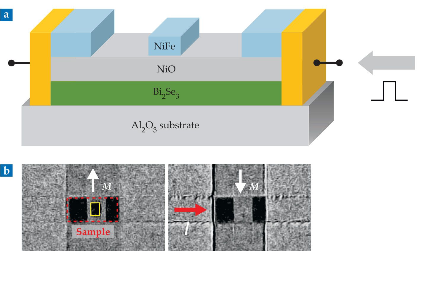
Figure 2.

Magnons flip the magnetization of a nickel–iron alloy magnet in the device shown in (a). An electrical pulse (gray arrow) creates electrical spin currents in the bottom bismuth selenide layer, and those currents induce magnons in the nickel oxide layer that travel up into the NiFe magnet. In magneto-optical Kerr effect images (b), before the magnons are introduced (left), the magnet’s magnetization M (yellow rectangle) is up (black). After the electrical pulse I (red arrow) induces magnons (right), its magnetization is down (gray). (Adapted from ref.
Yang and his group didn’t see the enhancement for reasons not yet clear. For thicknesses up to 10 nm, the electron torque did decrease for thicker NiO layers, as expected. They were surprised to find that spin torque experienced by the magnet increased monotonically as the thickness increased from 10 nm to 25 nm, peaking at about half the maximum value. That was their first indication that magnon spin torque was present and nearly as strong as the electron torque.
The group’s MOKE maps revealed that magnon spin-transfer torque is strong enough to flip the magnetization of an entire magnet (yellow rectangle in figure
Up next for magnons
Spin-wave control of magnetization offers many potential applications. For example, in an all-magnon device, spin waves could modulate the transmission of subsequent ones by moving the domain wall. Or they could be detected through changes in the magnetization rather than through small changes in the electrical resistance.
But first, the process of creating spin waves in a material needs to become more efficient. According to Liu, the solution for efficiently inducing spin waves will come down to developing easy-to-fabricate materials with the right properties, such as low damping and high magnetic anisotropy, and new techniques, such as voltage-controlled magnetic anisotropy.
References
1. See, for example, T. Schneider et al., Appl. Phys. Lett. 92, 022505 (2008). https://doi.org/10.1063/1.2834714
2. J. Han et al., Science 366, 1121 (2019). https://doi.org/10.1126/science.aau2610
3. Y. Wang et al., Science 366, 1125 (2019). https://doi.org/10.1126/science.aav8076
4. R. Hertel, W. Wulfhekel, J. Kirschner, Phys. Rev. Lett. 93, 257202 (2004). https://doi.org/10.1103/PhysRevLett.93.257202
5. S. S. P. Parkin, M. Hayashi, L. Thomas, Science 320, 190 (2008). https://doi.org/10.1126/science.1145799
6. H. Wang et al., Phys. Rev. Lett. 113, 097202 (2014). https://doi.org/10.1103/PhysRevLett.113.097202


