Collaboration unlocks self-replicating crack patterns
DOI: 10.1063/PT.3.2572
Surface coatings, found on everything from painted walls to computer chips, often build up residual stresses during deposition, drying, or mechanical loading. If the stresses become large enough, the film can fracture, which typically leads to a disordered crack pattern. But under the right conditions, regular patterns like the ones in the optical microscope images shown on page 19 can appear.

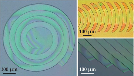
Optical microscope images of 0.5- to 10-µm-thick glass coatings deposited on silicon substrates reveal unusual spiral, crescent-shaped, and parallel-band crack patterns. The patterns result from a novel collaborative mechanism in which fracture and film delamination occur simultaneously. Interference fringes appear and move in each pattern as the film peels up from the underlying substrate and later settles back down. (Adapted from ref.
Joël Marthelot (now at MIT), Benoît Roman, and José Bico of ESPCI ParisTech, along with their colleagues from the Saint-Gobain Corp and the University of Santiago, have taken a close look at the formation of such cracks. The material they studied was so-called spin-on glass (SOG)—a silicate coating commonly used for electronic components—deposited on a silicon substrate. What they discovered was a new fracture mechanism that has implications for understanding the stability of thin films and offers the possibility of novel applications. 1
Although unusual, the crack patterns aren’t new. 2 In fact, Roman and Bico were introduced to them in 2006 by Melanie Lebental of École Normale Supérieure de Cachan. Lebental had been using SOG as an optical buffer layer for microlaser cavities as part of her PhD work when she noticed a sample covered with crescent-shaped cracks that zigzagged back and forth. “I had never heard of such cracks,” Lebental says. So she showed them to a friend, who introduced her to Roman. She visited Roman and Bico in their lab: “I gave them a sample with cracks, a small bottle of SOG, and the procedure to get the cracks.”
Lebental’s crack patterns looked similar to ones that Roman had studied before, 3 but those were produced by running a blunt cutting tool through brittle sheets with no substrate. (For more on the elastic properties of thin sheets, see the article by Michael Marder, Robert Deegan, and Eran Sharon, Physics Today, February 2007, page 33 .) “So the problem here was clearly different,” Roman says.
A tale of two cracks
Crack formation in thin films is usually a matter of competition between elastic energy and fracture energy. Residual tensile stresses often build up during film deposition and processing. If they grow large enough, the elastic energy released by cracking can overcome the energy needed to break the film. In the standard picture, the film fractures along isolated straight lines and stress is released only near the crack. New cracks tend to turn and run into old cracks perpendicularly. The result is the kind of crack pattern commonly seen in drying mud or varnish on old paintings. (For more, see the article by Lucas Goehring and Stephen Morris on page 39 .)
For a given film and substrate, the elastic energy is a function of stress and film thickness. So the balance between elastic energy and fracture energy prescribes a critical film thickness, below which an isolated crack shouldn’t propagate. But in their new study, Marthelot and company saw their nonstandard crack patterns even in films thinner than the critical thickness, which was 1.8 µm in their case.
The explanation came from realizing that the rules change for a pair of cracks. Two cracks running next to each other can release additional stress by having the film peel up from the substrate in the area between the cracks. “The propagation occurs thanks to the cooperation between the delamination and the crack propagation,” explains Marthelot. And that “collaborative” process allows an initial crack template to replicate itself: New cracks run parallel to previous fracture paths, with the distance between cracks governed by the thickness of the film. Enough new cracks and you get a parallel band, as seen in the lower right panel of the
Fracture energy is a property of the film, but varying film thickness changes the elastic energy and chemically pretreating the substrate can change the adhe-sion energy. Armed with those two control knobs, the group has explored the parameter space of elastic energy, fracture energy, and adhesion energy to see where films should be safe from cracks. “We provide a novel and more general condition for the stability of thin films,” says Marthelot. And the new criteria might be particularly relevant to technologies like stretchable electronics, because films tend to be less strongly bonded to flexible substrates and could develop bigger stresses during use.
But what about spirals and crescent shapes? Aren’t they isolated cracks? The trick is for a crack to follow its own previous path at a given distance. For a crack that initiates at a point defect, the result is a spiral, as shown in the left panel of the
The new fracture mechanism, the researchers suggest, could turn cracks—usually considered a nuisance—into a novel design tool to tailor surface microstructures. It could be used to make small objects like microsprings from spirals and cantilevers from parallel bands, and the crack paths themselves could be used as nanofluidic channels in medical applications. The challenge now is to get a better handle on initiating specific crack patterns. Marthelot says the team plans to try out several ideas, including intentionally putting in defects on the substrate prior to deposition, scratching the film with an atomic force microscope tip, and using a femtosecond laser to cut the film.
References
1. J. Marthelot et al., Phys. Rev. Lett. 113, 085502 (2014). https://doi.org/10.1103/PhysRevLett.113.085502
2. M. Sendova, K. Willis, Appl. Phys. A 76, 957 (2003); https://doi.org/10.1007/s00339-002-1757-1
N. Wan et al., Phys. Rev. B 80, 014121 (2009). https://doi.org/10.1103/PhysRevB.80.0141213. B. Audoly, P. M. Reis, B. Roman, Phys. Rev. Lett. 95, 025502 (2005).https://doi.org/10.1103/PhysRevLett.95.025502


