Better batteries through architecture
DOI: 10.1063/PT.3.3285
How well a battery works isn’t just about how much energy it can store. Among other factors, how fast the battery can deliver its stored energy is particularly important for electric cars and other high-power applications. (See the article by Héctor Abruña, Yasuyuki Kiya, and Jay Henderson, Physics Today, December 2008, page 43 .) In lithium-ion batteries those measures depend on how many, and how quickly, Li+ ions can be inserted into and extracted from the anodes and cathodes.
A lithium-ion battery’s electrochemically active components are the two electrodes—typically graphite for anodes and a Li metal oxide for cathodes—and the electrolyte layer in between. Standard electrodes consist of densely packed micrometer-sized particles and a labyrinthine network of electrolyte-filled pores.
In a charged battery, Li atoms reside in the spaces between graphite’s hexagonal layers. As the battery pushes electrons through an external circuit to do work, Li+ ions exit the graphite and head toward vacancy sites in the Li metal oxide. When the battery is charging, the opposite happens. If the electrolyte layer is the main thoroughfare for Li+ traffic, the pore networks are the side streets and alleys that wind past individual nanoparticles.
Most battery researchers have focused on improving electrode chemistries. (See the article by Matthew Eisler on page 30 .) Two groups, one led by Claire Villevieille at the Paul Scherrer Institute and André Studart at ETH Zürich and the other led by Yet-Ming Chiang at MIT and Randall Erb at Northeastern University, have chosen to optimize the electrode structure instead. Both groups used magnetic alignment to produce more-direct ion-transport paths. The Swiss collaboration 1 worked on graphite anodes whereas the US group 2 worked on lithium cobalt oxide cathodes. Their strategies to engineer better electrode architecture portend an alternative route to increased electrode performance.
Tortuous pores
Thicker electrodes can accommodate more Li, but at a cost: The ions have to travel farther through the maze of pores. At some point, the inefficient Li+ transport can’t keep up with the power demand, and any added storage space from making the electrode thicker is wasted. For many practical applications, electrode thickness is limited to about 0.1 mm.
Tortuosity is the measure of a meandering path’s twistiness. In battery electrodes, greater tortuosity means Li+ ions must travel longer distances to get into or out of the electrodes. The Swiss and US groups both reasoned that aligning the pores would reduce tortuosity and thus improve the electrode’s effective ion conductivity.
To make low-tortuosity anodes, Villevieille, Studart, and their colleagues took advantage of graphite’s natural tendency to come in flakes. They attached iron oxide nanoparticles to graphite platelets. The superparamagnetic nanoparticles are so small that thermal fluctuations randomly flip their magnetization directions. So when they’re suspended with the graphite in a solvent, they don’t clump together. Once the nanoparticles attach to a graphite platelet’s surface, applying a magnetic field fixes their magnetization directions such that the platelet appears to have a single in-plane dipole moment.
An external magnetic field can thus align the platelets. But even if a vertical field aligns the platelets’ dipole axes, their faces can still orient along any horizontal direction. That unwelcome spread in orientation results in poor packing. To get the platelets to all face the same way, Villevieille, Studart, and their colleagues rotated the magnetic field.
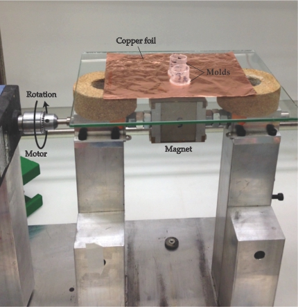
As shown in figure 1, the researchers placed a motor-mounted permanent magnet just below a copper foil onto which they cast their graphite suspension. When the magnet is rotated, the dipole moments follow the field and the platelets tumble in place, end over end. However, at sufficiently high rotation rates, the platelets can no longer keep up. “You’re into a nonequilibrium state where the platelet doesn’t know what to do,” explains Studart.

Figure 1. Graphite platelets coated with magnetic nanoparticles and suspended in a solvent were cast onto a copper foil in plastic molds. A motor rotates a permanent magnet below the foil, and the rotating magnetic field aligns the platelets. (Adapted from ref.
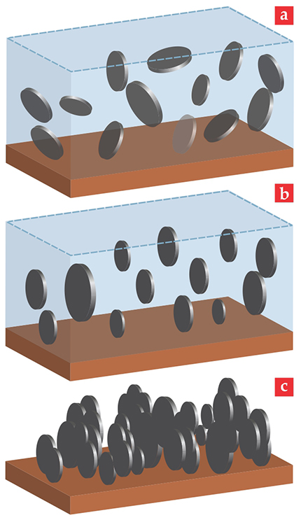
The lowest-energy configuration is for the planes of the platelets’ faces to align with the plane of the field’s rotation, as shown in figure 2. Drying the suspension in the rotating field ensures that the solid anode retains the alignment. The pores that form between the platelets thus present an easy path for the Li+ ions to get to the graphite. In addition, the orientation of the platelets presents ready access points for the Li+ ions to enter the graphite’s layered structure.

Figure 2. Magnetic alignment of graphite anodes. (a) Initially, the suspended graphite platelets are randomly oriented. (b) In a quickly rotating magnetic field the platelets lower their energy by facing the field’s rotation axis. (c) When the solvent evaporates, the aligned platelets pack down together into a compact array. (Adapted from ref.
Graphite, in principle, can accommodate one Li atom for every six carbon atoms. But the usable fraction of that capacity varies with charge and discharge rates, usually quantified as the C-rate: 1C means going from full charge to full discharge in one hour, 2C means twice that rate, and so on.
The Swiss group’s first batch of 0.2-mm-thick anodes demonstrated a charge capacity of nearly 2 milliamp-hours per square centimeter of surface area at a C-rate of C/10 and about 0.4 mAh/cm2 at 2C. Although some commercial anodes can do better than 2 mAh/cm2, Studart notes that they can’t run faster than 1C. Moreover, the prototype anodes, other than being aligned, were not optimized. The group is now testing for the best platelet sizes and looking at ways to improve the graphite packing density.
Cross pollination
The Swiss and US groups worked independently but with some notable exchanges. Jonathan Sander, the lead author on the US paper, completed his PhD thesis with Studart. And Erb coinvented the technique for magnetically aligning platelet-shaped material when he was a postdoc in Studart’s group. 3
When Sander, who had done his master’s work with Chiang, returned to MIT for a postdoc, he brought with him a fellowship from the Swiss government to work on magnetic alignment of electrode material. Chiang challenged Sander to find a new idea. Sander came up with two.
In one approach, the researchers coated nylon microrods with magnetic nanoparticles. They mixed the microrods in with a suspension of lithium cobalt oxide, a common cathode material, and lined up the rods vertically with an external magnetic field. Once the suspension was dried, the microrods were burned away to leave behind straight pores running through the cathode.
In another approach, the researchers added an oil-based suspension of iron oxide nanoparticles into their alcohol-based suspension of cathode material and emulsified the oil. In an applied magnetic field, the fine emulsion droplets spontaneously formed into aligned linear chains; drying the suspension removed the ferrofluid and, again, left behind a solid cathode full of straight pores.
In both approaches, the researchers baked the solidified material to improve packing density. The finished solid cathodes contain linear pores that run from one end to the other and a network of finer pores that branch out laterally. The scanning electron microscopy images in figure 3 show cathodes made with the two techniques.

Figure 3. Linear pores built into lithium cobalt oxide cathodes can be seen in these scanning electron microscopy images. (a) An external magnetic field aligns 10-μm-diameter nylon microrods coated with iron oxide nanoparticles in a suspension of powdered cathode material. This side view shows the pores left behind after the suspension dries and the microrods have been burned away. (b) Alternatively, emulsified ferrofluid droplets can replace the microrods. A magnetic field induces the emulsion droplets to spontaneously form aligned, linear chains. Drying the suspension removes the emulsion droplets. (Adapted from ref.

For C-rates greater than C/2, the aligned cathodes had up to three times the capacity of unaligned ones. In addition, Chiang and his colleagues took 0.2-mm-thick cathodes made with the microrod technique and put them through a series of charge and discharge steps that simulate use in an electric car. At those conditions, the aligned cathodes demonstrated usable capacity up to 8.1 mAh/cm2, more than twice that of conventional cathodes.
From lab to factory
Chiang and his collaborators have since figured out how to skip the post-alignment baking step. Doing so, Chiang explains, should make their magnetic alignment techniques simpler to incorporate into existing manufacturing processes.
Whether the newly developed methods make it out of the lab and into the real world will also depend heavily on the cost of adding manufacturing steps and retrofitting equipment.
Chiang suggests that one source of cost savings could be reduced materials consumption. About 25% of a battery cell is made up of the metal foils that act as current collectors, the polymer separator placed between the electrodes to prevent shorts, and other inactive components. Thicker electrodes could bring that fraction down to 5% for a cell with the same physical size, Chiang explains, and that reduction “can amount to a 30–35% reduction in the materials cost of the cell.”
References
1. J. Billaud et al., Nat. Energy 1, 16097 (2016). https://doi.org/10.1038/nenergy.2016.97
2. J. S. Sander et al., Nat. Energy 1, 16099 (2016). https://doi.org/10.1038/nenergy.2016.99
3. A. R. Studart, R. M. Erb, R. Libanori, “Method for the production of reinforced materials and reinforced materials obtained using the method,” US Patent 8,889,761 (18 November 2014).


