A strain-based antenna paves the way for portable long-range transmitters
DOI: 10.1063/PT.3.4244
Very low-frequency (VLF) radio waves can carry signals through land and water with little attenuation. Unlike higher-frequency electromagnetic waves used for most communications, VLF waves are reflected by the ionosphere, and the space between it and Earth’s surface acts as a waveguide through which the waves travel beyond the horizon. So, whereas higher-frequency waves travel in straight lines, VLF signals follow Earth’s curvature and can transmit information to locations hundreds of kilometers away. The military uses VLF waves for navigation and communication with aircraft and submarines.
Although VLF signals are routinely generated, their use is limited by an antenna’s size. To be reasonably efficient, an antenna’s length should be at least a tenth of the signal’s wavelength. For VLF waves, which are 3–30 kHz, the length would be more than a kilometer. Antennas whose length is much less than the signal’s wavelength are considered “electrically small.” They can still transmit VLF waves, but their nonradiative losses are large compared with the signals they transmit, so electrically small antennas are much less efficient than their larger counterparts. The VLF antennas used by the military are hundreds of meters tall, and even at that size they’re electrically small. If they were portable, VLF antennas could be used by divers underwater, or by soldiers moving through underground mines or caves.
With their new piezoelectric antenna, Mark Kemp and coworkers at SLAC and their two industrial collaborators, SRI International and Gooch and Housego, are trying to get the best of both worlds.
1
Their prototype 9.6-cm-long lithium niobate transmitter, shown in figure
Figure 1.

The portable piezoelectric transmitter in the foreground use mechanical oscillations in a lithium niobate crystal (clear rod) to generate very low-frequency radio waves. Researchers had to take the transmitter to a remote location far from buildings and power lines to get accurate measurements of its field. In this photo, Alex Nguyen is using a receiver to measure and determine how the field drops off as a function of distance. (Photo courtesy of Dawn Harmer/SLAC.)

Vibrating crystals
Piezoelectric crystals are often used as electronic oscillators because they vibrate with precise frequencies. Quartz crystals, for example, began being used about a century ago for timekeeping and as frequency references for radio stations. Vibrations in piezoelectric crystals are generated by an electric field that causes the atoms to shift in each unit cell and thereby deform the crystal. That shift also causes charge separation, and a voltage difference develops between the ends of the crystal. When the field is removed, the crystal returns to its original state. Oscillating the electric field generates a periodic voltage and strain. If the field oscillates at the piezoelectric resonance of the crystal, which depends on its mechanical and electrical properties, the deformation and peak voltage are maximized. In a quartz watch, the timing of those voltage peaks determines the length of a second.
The LiNbO3 crystal used by Kemp and colleagues works on the same principle. Applying an alternating voltage causes the crystal to vibrate at its resonant frequency. The vibration induces a large electric field in the crystal because of LiNbO3’s strong electromechanical coupling. As the electric field in the crystal oscillates, the crystal radiates as an electric dipole, just like a wire antenna. However, whereas conventional antennas radiate because they carry a current of flowing charges, strain-based antennas radiate because of a displacement current, or time-varying electric field, created by bound charges in the material. 2
Connecting an antenna directly to an impedance-mismatched power source causes signal reflection and the formation of standing waves in transmission lines. 3 Impedance matching the source and the antenna by adding the right combination of capacitors and inductors minimizes the problem and maximizes the power radiated by the antenna. But those additional circuit elements can be bulky and have their own associated losses. For a metal VLF antenna that would be small enough to carry, the size of and losses from the circuitry would be prohibitively large.
A piezoelectric resonator, however, eliminates the need for extra impedance-matching elements. The crystal behaves like an electrical circuit with a resistor, inductor, and capacitor, and the effective circuit’s impedance can be tuned by varying the crystal’s size, stiffness, and mechanical friction. A large impedance-matching inductance is therefore embodied by the antenna itself.
A measure of success
Radiation efficiency is proportional to the energy radiated and inversely proportional to its nonradiative losses. Switching to a piezoelectric material reduced the nonradiative losses in Kemp and coworkers’ antenna by a factor of about 300 compared with a similarly sized metal antenna. That improvement came from using LiNbO3, which has low mechanical elastic losses, removing the impedance-matching circuit, and choosing to excite a particularly low-loss vibrational mode in the antenna.
Reducing nonradiative losses should improve the overall efficiency of the antenna. But confirming that expectation requires measuring the radiated field at a distance comparable to the wavelength, which the researchers have not yet done. “Measuring the fields precisely is a challenge,” says Kemp. “Any RF interference or materials around the transmitter and receiver can significantly alter the measurement. For many of our experiments, we had to go out to fields far away from power lines and buildings.” Measurements of the field out to 80 m indicate that, like a metal antenna, the piezoelectric antenna radiates as a dipole. The researchers are therefore optimistic that upcoming far-field measurements will confirm their antenna’s 300-fold increase in efficiency.
Reducing nonradiative losses is important for increasing efficiency, but unfortunately it also decreases the antenna’s bandwidth. The piezoelectric resonator’s bandwidth is just 84 mHz, which would be prohibitively small for using frequency modulation to transmit audio signals. Even large VLF antennas have limited bandwidths and are used only for text-based messages. Information is often encoded in the signal using frequency-shift keying (FSK)—alternating between two distinct frequencies. In that case, the transmitter doesn’t need to work at a wide range of frequencies. It just needs to transmit strongly at two frequencies that can be distinguished from each other.
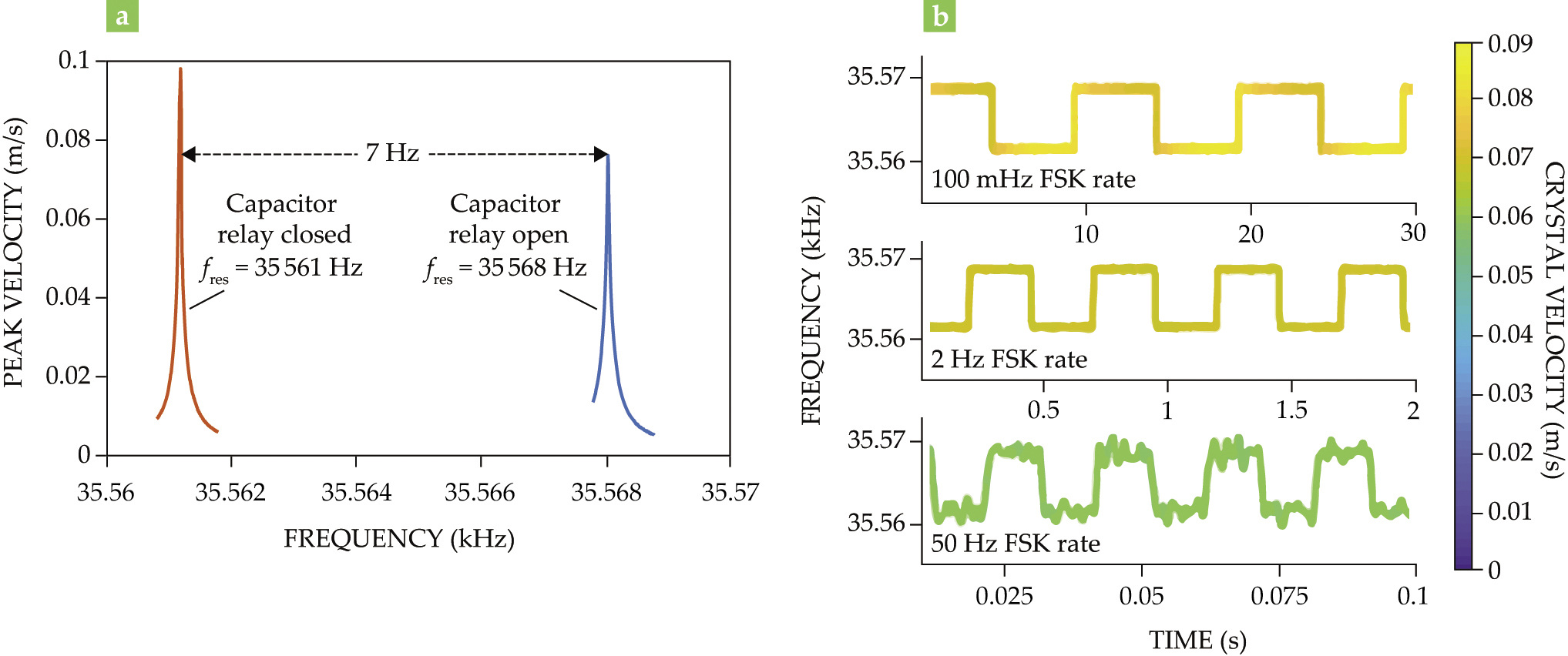
To improve the antenna’s effective bandwidth—the separation between usable transmission frequencies—the researchers modulated its resonant frequency fres between two values by coupling it to a capacitor through a relay. Modulating fres between 35.561 kHz and 35.568 kHz, as shown in figure
Figure 2.

Antenna modulation increased the bandwidth of the piezoelectric transmitter. (a) Opening and closing a capacitor relay changes the resonant frequency fres of the transmitter and allows it to oscillate at two easily distinguishable frequencies. (b) Frequency-shift keying (FSK)—alternating between two distinct frequencies—can encode information in narrowband signals. The transmitter’s two resonant frequencies are easily distinguishable at all three FSK rates shown. However, at higher FSK rates, the velocity at which the crystal oscillates, and therefore the antenna’s power output, decreases. (Adapted from ref.
Like all antennas, piezoelectric antennas are inherently reciprocal, meaning that they can serve as both transmitters and receivers. But antenna modulation breaks that reciprocity. If the resonant frequency of the antenna isn’t modulated along with the transmitter, it will only receive one of the frequencies. But knowing when to modulate the receiver would require already knowing the incoming signal pattern. Small conventional receivers already exist though, so the lack of reciprocity is not a problem.
The next phase
Although strain-powered antennas were first proposed more than 50 years ago, 4 Kemp and his collaborators took up the project recently thanks to the A Mechanically Based Antenna (AMEBA) program. Announced by the Defense Advanced Research Projects Agency in 2016, the AMEBA program drives fundamental research into mechanical antennas and antenna miniaturization, an area that hasn’t seen much progress in recent years. 5 In line with the program’s goals, Kemp says, “We target human-portable, long-distance communication with as small of a package as possible.”
The researchers’ project recently moved out of exploratory phase I and into developmental phase II, so they expect to continue pushing the limits of electrically small antennas. “At each phase, we will further increase the bandwidth and radiated power,” says Kemp. A larger frequency separation would allow for better signal quality at higher FSK rates and give the researchers more flexibility in choosing a modulation scheme. In the coming year, they expect to improve both metrics by a factor of 10.
References
1. M. A. Kemp et al., Nat. Commun. 10, 1715 (2019). https://doi.org/10.1038/s41467-019-09680-2
2. J. P. Domann, G. P. Carman, J. Appl. Phys. 121, 044905 (2017). https://doi.org/10.1063/1.4975030
3. J. S. Seybold, Introduction to RF Propagation, John Wiley & Sons (2005).
4. J. H. Rowen, F. G. Eggers, W. Strauss, J. Appl. Phys. 32, S313 (1961). https://doi.org/10.1063/1.2000450
5. Defense Advanced Research Projects Agency, “Underwater radio, anyone?” (16 December 2016).


