Water in polymer electrolyte fuel cells: Friend or foe?
DOI: 10.1063/1.2387087
The motor runs using water? asked the Commissar.
Sure, kerosene stokes, water cools off.
Use less kerosene and more water, rationalized the Commissar.
—Andrei Platonov, Concealed Man
The motor runs using water? asked the Commissar.
Sure, kerosene stokes, water cools off.
Use less kerosene and more water, rationalized the Commissar.
—Andrei Platonov, Concealed Man
Almost a billion years ago, Nature engineered an ingenious solution to the problem of converting chemical energy to mechanical energy in living things: the creation of a gradient in the concentration of protons across mitochondrial membranes. Human beings came up with a radically different solution just prior to the Industrial Revolution: the heat engine and its conversion of thermal energy from a chemical reaction into work. Steam engines, first patented in 1698, could provide vast amounts of power for locomotives and industrial processes. The trouble was that the steam engine’s need for large amounts of water as a working fluid limited its practical use to large installations. It wasn’t until Nikolaus Otto in 1861 and Rudolf Diesel in 1897 devised the two earliest variants of the internal combustion engine that engineers could circumvent the need to carry around tons of water. Engine sizes shrank in response, which kick-started the motor-vehicle industry with all its eventual consequences, including societies’ dependence on fuel resources and the world’s changing environment.
In 1838, however, decades before the age of combustion engines and not long after that of steam engines, two scientists discovered a different method of converting chemical energy into work (see
Indeed, water is the lifeblood of the fuel cell, though its role is double-edged. It is transported into the fuel cell as part of the reactants, but it is also a product of the overall reaction. It exists as a liquid in the polymer electrolyte that separates the anode and cathode, but also equilibrates with the gaseous reactants that flow through the electrodes and supporting structures in the fuel cell. The transport of water is driven by diffusion, electro-osmotic effects (the drag that water molecules experience due to the migration of hydrogen ions), pressure gradients, and electrochemical reactions.
Without sufficient water in the polymer electrolyte and catalyst layers, proton transport and reactivity are poor, causing performance to suffer. Moreover, the excess heat produced by inefficient operation hastens the fuel cell’s degradation—the cell dries out and dies. Excess liquid water in the catalyst and porous transport layers, though, also impedes reactant transport. Unable to continue operating with water clogging “breathing” channels, the fuel cell drowns. Under freezing conditions, the water may solidify into ice; care must be taken to prevent that phase transformation from destroying the integrity of the cell.
Put poetically, fuel cells, like people, can’t afford to dehydrate, yet they also run poorly when too much water is present. So one of the main goals in fuel-cell design is to maintain a proper water balance in all components. Engineers must account for competing hydration requirements of the polymer electrolyte, the porous electrodes, and surrounding supporting structures. A further design complication is that the cell must stay optimally hydrated while its power output varies to match the changing requirements of an external load. That variation in turn affects the cell’s flow rates and internal temperature.
The trick, then, is to figure out what designs and operating conditions optimize cost, performance, and water management. That’s not easy. It requires detailed understanding of fundamental processes and how they are spatially distributed in the cell. In this article, we discuss the main issues associated with water generation and transport in solid polymer electrolyte fuel cells and elucidate the areas in which significant improvements may be possible.
The genesis of fuel cells
In the December 1838 issue of Philosophical Magazine, Christian Friedrich Schönbein, professor of physics and chemistry in Basel, Switzerland, reported the first observation of the fuel-cell effect—the generation of water and energy from a recombination of hydrogen and oxygen. A month later the same journal published a brief account of the same effect and the first design of a fuel-cell generator of electrical current. The author was then a barrister William Robert Grove, later a professor of physics at the London Institution. The main difference between the two setups was that Grove directly provided a gas feed of hydrogen and oxygen to the corresponding electrodes and thereby demonstrated the existence of a process that was the reverse of electrolysis. The engineering principle of that setup lies at the heart of the modern fuel cell.
In the history of science, Schönbein is better known for the invention of guncotton and the discovery of ozone. Grove is solidly recognized as the inventor of the fuel cell; his priority to Hermann von Helmholtz on the law of energy conservation is usually forgotten. Schönbein and Grove were friends, connected by years of correspondence. They both deeply understood the meaning of their discovery. If the Nobel Prize had existed at the time, they would have deserved equal shares.
Fuel-cell design
Modern polymer electrolyte fuel cells and direct methanol fuel cells use proton-conducting polymer electrolyte membranes to power portable, vehicular, and small residential applications (see the article by Sivan Kartha and Patrick Grimes in Physics Today, November 1994, page 54 ). Solid oxide fuel cells, the other major type, based on high-temperature O2− ion-conducting oxides, are best suited for larger-scale stationary applications and are not considered here.
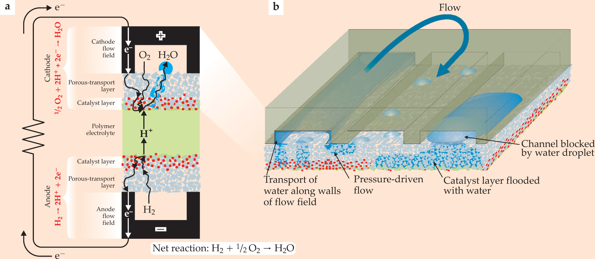
Hydrogen in a polymer electrolyte fuel cell, or methanol in a direct methanol fuel cell, is oxidized in the catalyst layer on the anode side of the fuel cell. The resulting protons and electrons are forced onto separate paths to the cathode, where they recombine with oxygen to produce water. Figure 1 depicts the reactions in a hydrogen-based polymer electrolyte fuel cell. The activation of kinetically hindered reactions such as oxygen reduction or methanol oxidation dissipates energy at the electrodes. The migration of protons through the polymer electrolyte and catalyst layers also dissipates energy, as does the diffusion of reactant and product molecules and permeation of liquid water. These kinds of losses prevail during normal operation.

Figure 1. This polymer electrolyte fuel-cell circuit, in cross section (a), illustrates the cell’s anatomy. The flow fields, electrical plates etched to form open channels that disperse hydrogen or oxygen gas to the cell, form the base of the anode and cathode. Sandwiched between the top and bottom channels are two layers of catalysts (red) where oxidation (on the anode side) and reduction (on the cathode side) occur. In the middle, a proton-conducting polymer electrolyte channels hydrogen ions through the cell. Water (blue) produced in the cathode percolates through the catalyst and porous-transport layers into the flow channel, where it can form droplets or coat the sides and allow gases to flow freely, as pictured in (b). The more detailed rendering illustrates the cathode’s flow-field channel folded into continuous parallel sections. Pressure differences between the sections can drive water under the ribs of the channel. Excessive water that accumulates can flood the porous-transport and catalyst layers and block the flow of gases in the channel.
The more dramatic potential drops that occur at large current densities are often a consequence of insufficient transport of reactants and products. Subtracting all the irreversible losses from the thermodynamic free energy E th that is released in the overall reaction yields the net free energy or electrical cell potential that could be put to work in an external electrical device: E = E th − V(J). The function V(J) increases with the current J drawn from the cell due to inefficient delivery of reactants and removal of products, and it is also affected by the concentration of reactants, operating temperature, reaction kinetics, and activity of the catalysts. 1
Catalyst layers
The catalyst layers regulate the traffic and conversion of hydrogen gas (or methanol) at the anode and oxygen at the cathode. The story of water’s journey through a fuel cell ought to start in the cathode catalyst layer, as that is where it is produced during the reduction of oxygen. That reaction is, moreover, what most hinders the performance of hydrogen-fed cells and leads to a major portion of the irreversible potential losses.
Oxygen reduction is a multistep process. It requires the transport of oxygen molecules, protons, and electrons through diffusion and conduction to the catalyst surface, where gas molecules adsorb and charge transfer occurs—all in the presence of water. Water as a reaction product then desorbs and diffuses away through the channels. Hydrogen peroxide, an undesired intermediate during oxygen reduction, may also be formed in either the anode or cathode; highly aggressive, hydrogen peroxide can degrade the polymer electrolyte. 2
A detailed balance of all those stochastic processes affects the overall rate of electrochemical conversion. Suitable catalysts must remain stable in a hot, oxidizing, acidic, aqueous environment, while effectively driving the production of water and resisting deactivation caused by the poisoning effects of fuel contaminants and atmospheric pollutants.
Precious metals and alloys, specifically those that incorporate platinum, have historically shown the best balance of catalytic properties. Catalysts should exist in a form that exposes a large interfacial surface area. Irreversible voltage losses during sluggish reactions such as oxygen reduction depend in a roughly logarithmic way on the local current density. A larger catalyst surface area thus reduces those losses. Practically speaking, increasing the surface area by a factor of 10 ideally decreases losses in voltage by about 60–120 mV (120 mV is about 10% of E th); the precise value depends on the energetics of the rate-limiting charge-transfer step. 2
The minimum particle size that can be produced, however, has limits. Individual particles smaller than 5 nm spontaneously coalesce with adjacent particles to minimize the surface free energy. To avoid the problem, individual catalysts as small as 2 nm can be stablized on an electronically conductive support, which keeps them apart. Carbon is the preferred support because of its corrosion resistance, its high conductivity, and the ease with which it can be nanostructured.
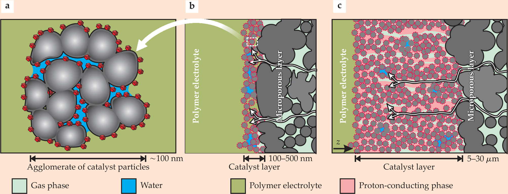
All species—the various gases, electrons, and ions—that participate in the reactions must access the catalyst surface. But no single homogeneous phase or percolating network can transport those different species simultaneously. Catalyst layers must therefore be incorporated into a composite structure with a minimum of two distinct phases: The first, the solid phase of carbon and platinum, conducts electrons. Water, filling the pore spaces in the composite could, by itself, serve as the second phase to transport protons, hydrogen and oxygen gas, and other water molecules.
These kinds of two-phase composite layers work well as long as they are extremely thin—100–500 nm or so. If they are too thick, the diffusion of dissolved reactant molecules and protons is slow and the cell inefficient; but if they are too thin, they may not provide a sufficient reaction surface. It is also difficult to produce thin composite structures over the large areas required for a fuel cell. Catalyst layers as thick as 5–30 µm are more typically produced. To preserve the cell’s efficiency, it is necessary to combine three independent percolation networks—one for electrons, one for protons, and one for reactants and products. Solid carbon and platinum transport electrons to the catalyst, whereas a second, solid subphase, typically composed of the DuPont company’s polymer Nafion, provides sufficient proton conduction. Making the catalyst layer porous—to create the third percolation network—allows gases to readily diffuse among the catalysts. Researchers have reduced the amount of catalyst packed into a cell from 4 mg/cm2 to less than 0.4 mg/cm2 by empirically optimizing such composite structures.
Within the composite structures, parameters such as reaction rates, concentrations of reactants and products, and electrode potentials are nonlinear, spatially distributed functions. Percolation properties of the three interpenetrating networks determine reaction and transport properties. Water competes with reactant gases for space between the solid components, and the degree to which liquid water penetrates the catalyst layer depends on the pore-size distribution, wetting properties, and operating conditions—current density, fluxes of gases and water, and partial pressures. The ability of catalyst layers to direct water into the membrane material rather than the channel or to facilitate its evaporation affects the overall water and heat management of the cell.
Empirical optimization studies indicate that cathode catalyst layers generate the maximum power density when roughly one-third of their volume is filled with proton conductor and they are between 10 and 20 µm thick. A bimodal porous structure with intra- and inter-agglomerate pores, as sketched in figure 2, seems to provide the best results.

Figure 2. Structure and composition of catalyst layers. (a) Carbon (gray) coated in platinum catalysts (red) forms the roughly 100-nm agglomerates that cluster together to compose the catalyst layer in a polymer electrolyte fuel cell. (b) If the pores in an agglomerate fill with water (blue), then the layer must be designed quite thin—between 100 and 500 nm—to account for the reduced rates of gas transport through liquid water. (c) Secondary pores, 10 to 50 nm in diameter, form between agglomerates in the course of the spontaneous aggregation of carbon particles. A percolating fraction of water-free secondary pores can enhance reactant transport by up to three orders of magnitude due to gaseous diffusion. A much thicker 5- to 30-µm layer can then be used. A proton-conducting phase (pink), which may be the polymer electrolyte, must coexist with the gas phase in the thicker catalyst layer to enhance proton transport. Thick or thin, the catalyst layer must allow distinct species—liquid water, hydrogen ions, electrons, and gases—to percolate through the cell. White arrows depict that percolation.
Even in three-phase composites that optimize the balance between large active areas and the transport of reactants, only 10–20% of the catalyst is used. Furthermore, not all parts of the catalyst layer perform equally well at a given current because of the competition between the charge transport, gas transport, and reaction kinetics; in effect, reaction rates vary as a function of depth in the catalyst layer. Thicker layers provide larger areas to support reactions, but they generally impede diffusion. Proper design strives for an optimum. Theorists and diagnosticians have taken a long time to establish such properties as the thickness of the catalyst layer, its porous structure, and the volume fraction of each of the three interpenetrating percolation networks. , Inhomogeneity in the lateral direction depends on the design of the flow field, and can, in principle, be reduced dramatically. Plenty of opportunity remains to further reduce the loading of catalysts through modeling and experimental efforts that map the spatial distribution of operational properties of the cell. 5
At the design level, theories of how reactants and ions percolate through the cell may suggest morphologies for ideal architectures, but one never knows whether such morphologies are realized in the hot-pressing or ink-painting techniques currently used in the fabrication of catalyst layers. Many researchers, therefore, view new well-defined architectures based on nanometer-scale template electrodes—using, for example, carbon nanotubes as building blocks—as the future in porous-electrode technology. For example, Mark Debe and coworkers at 3M have fabricated catalyst layers based on nanostructured substrates. The layers incorporate organic whiskers that have high surface-to-volume ratios. 6 They are consequently much thinner than conventional catalyst layers and are essentially two-phase composites. As much as 100% of the catalysts can be used.
Polymer electrolyte
Although water in gas-supplying channels and pores is usually an unwanted product that should be removed as quickly as possible, water in the polymer electrolyte serves as the proton shuttle. An important aspect of the design of catalyst layers, therefore, is to ensure that the product water is efficiently coupled to the polymer electrolyte, where it improves the mobility of hydrogen ions.
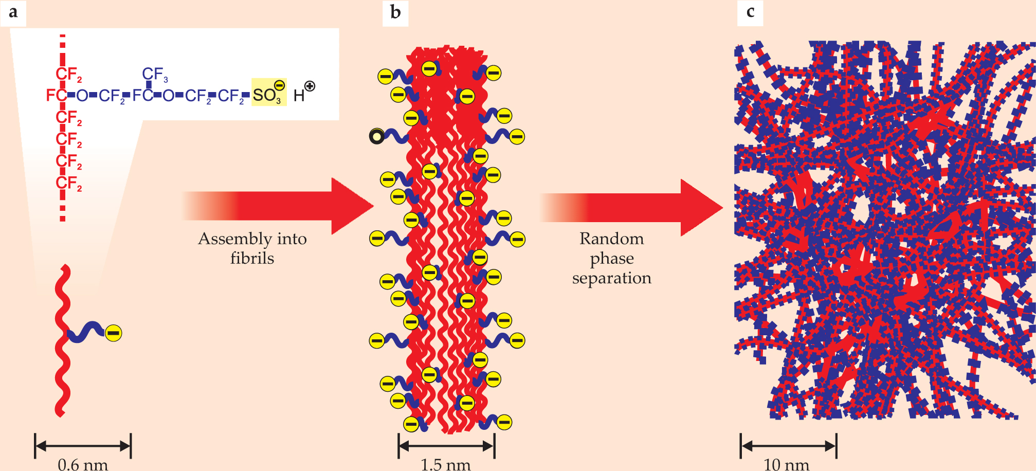
In conventional polymer electrolytes, polymeric side chains terminated by acidic hydrogen sulfonate groups are randomly tethered to hydrophobic polymeric backbones, as illustrated in figure 3. In the hydrated-membrane state, mobile protons (H+ ions) are formed from the dissociation of the HSO3 groups. The dissociation and proton mobility both require a sufficient amount of water (see

Figure 3. A typical polymer electrolyte. Nafion, pictured schematically here, consists of a hydrophobic fluoropolymer backbone (red) and a flexible side chain (blue) terminated by a hydrophilic sulfonate group (yellow). The polymer chains aggregate to form fibrils made up of a hydrophobic core surrounded by the ionized, hydrophilic side chains. In the polymer electrolyte, the fibrils agglomerate and randomly self-assemble into regions that are hydrophobic (mostly red) and hydrophilic (mostly blue). The interspersing of hydrophobic regions adds structural integrity to a hydrophilic composition designed to accommodate the water needed to conduct protons well without itself dissolving.
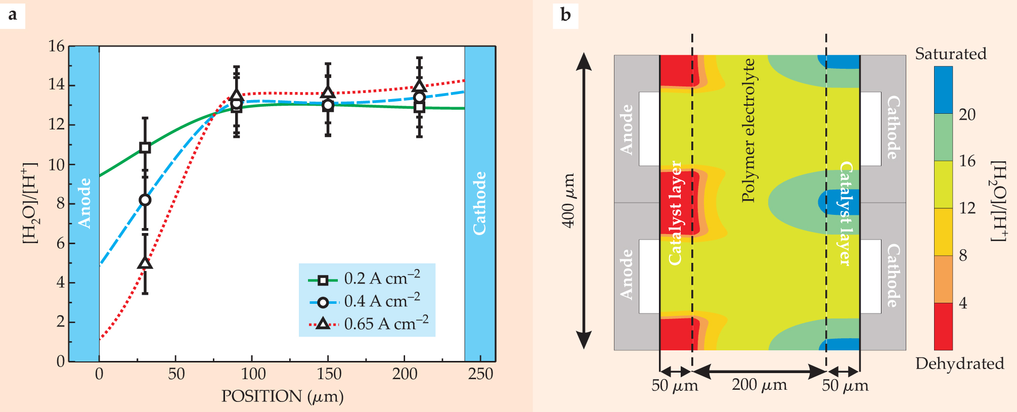
An additional complication is that water is not immobile, so proton migration is coupled to the transport of one or two water molecules in a process called electro-osmotic drag. This drag alongside the proton flux shuffles water molecules toward the cathode catalyst layer. A backward flux of water molecules toward the anode catalyst layer occurs from diffusion or pressure-driven flow that opposes the water shuffling toward the cathode. Consequently, an improper balance of electro-osmotic drag and back flux could dehydrate the catalyst layer near the anode or flood it near the cathode. Either detrimental effect could dramatically increase the cell’s voltage losses V(J) and even cause complete failure at high current densities. Theory 7 and experiments 8 have both confirmed the phenomena (see figure 4).

Figure 4. The ratio of the number of water molecules to hydrogen ions, plotted as a function of position across the cell, indicates the nonlinear distribution of water in the fuel cell. (a) The experimental plot reveals the extent to which the anode side of the polymer electrolyte dehydrates as the cell’s current density increases. A higher flux of protons and the attendant flux of water are dragged out of the anode region because of electro-osmosis that accompanies the higher current densities. Water saturates the membrane regions adjacent to the cathode catalyst layer. (b) The two-dimension simulation reveals a depletion of water around the ribs of the anode and its accumulation around the ribs of the cathode.
(Experimental data from ref. 8; simulation data from ref. 16.)
The flux of water in the polymer membrane depends in a complicated way on its morphology and current density. 7 Keeping all parts of the polymer electrolyte in a well-hydrated state, even under drastic variations in operating conditions, is a key task in a working polymer electrolyte fuel cell. Designing polymer membranes that experience a reduced amount of electro-osmotic drag would be an obvious solution to the water management problem. This could be accomplished by partially immobilizing the water in the membrane without impairing its conductive abilities. Alternatively, high rates of water back flux can be achieved by using thin membranes with a higher concentration of hydrophilic regions. 7 But such modifications often come at the cost of higher reactant permeability, less chemical stability, and reduced mechanical robustness.
Membrane practicalities and progress
Operating the cell at temperatures above 120 °C would enhance the kinetics of the electrochemical reactions at electrodes and make managing waste heat easier. A polymer electrolyte should also adapt to freezing conditions, including winter conditions in Alaska or Siberia. The mechanisms of proton transport change in such conditions because of the lack of liquid water in the membrane. The shortage of water creates higher activation energies in the fuel cell, high ohmic resistances, local overheating, strong temperature gradients, and thus both reversible and irreversible structural deformation of materials. In effect, the fuel cell wears out more quickly.
The polymer electrolyte should be cost-effective. For automobiles, a target of $10 per kilowatt for the membrane and electrodes 9 is currently out of reach. Today’s materials are about 10 to 20 times too expensive. Finally, the electrolyte should be recyclable when the fuel cell reaches the end of its life.
No known materials currently satisfy all of those requirements. Sulfonated and fluorinated polymer electrolytes come closest. The most famous of those is Nafion (see figure 3). To produce materials with properties superior to perfluorosulfonic acids, researchers have explored new routes in chemical synthesis, mainly on an empirical basis. But the consensus is that a deeper theoretical understanding of how the chemical architecture and morphology of Nafion and similar materials influence their transport properties could greatly facilitate the search. Most structural models of polymer electrolyte materials emphasize their phase-separated nature.
Much work has focused on understanding proton transport through water-filled pathways in presumably representative fragments of the polymer host. Nuclear magnetic resonance measurements of molecular mobilities and impedance spectroscopy, which probes the macroscopic conductivity, provide useful insight into mechanisms of proton transport. In particular, Arrhenius plots of conductivity in a cell at various water contents help with understanding the energetics of proton and water transport.
Elements of microscopic proton-transfer theory, ab initio density-functional and molecular-dynamics calculations, and statistical mechanics and continuum dielectric approaches have all been put to work in explaining the factor-of-three increase in activation energy of proton transport between a fully saturated and a dry membrane state. The thought is that in the saturated membrane, protons migrate freely through the almost bulk-like aqueous phase—with an activation energy around 0.1 eV. But as the membrane dries, proton transport takes place along narrow aqueous pathways near the
On the materials-science front, progress is also being made. Various research teams have produced materials that conduct protons well at temperatures exceeding 100 °C by virtue of inorganic proton-conducting fillers incorporated into the polymer electrolyte. 12 Strong polymer–water bonding in the materials prevents the water from boiling away at 100 °C. Furthermore, lamination of polymer electrolytes with different properties can help maintain a good water balance in the membrane.
It may be possible in the future to replace water with an alternative, organic proton-donor material. Klaus-Dieter Kreuer of the Max Planck Institute for Solid State Research in Stuttgart, Germany, has shown, for example, promising conductivity results in systems based on imidazoles, nitrogen-containing ring compounds in which the protons attached to the nitrogen atoms can be ionized. The measured conductivities, however, are still too low for use in fuel cells. 13 Other systems are candidates. Proton conduction is high in phosphoric acid at temperatures up to about 210 °C, and fuel cells based on that approach have been available for 30 years. Its modern counterpart, discovered by Robert Savinell and his colleagues at Case Western Reserve University, is a membrane made of a polybenzimidazole matrix—the same heat-resistant material in space suits and fire-fighting equipment—in which phosphoric acid dissolves. It performs well at temperatures exceeding 150 °C, although loss of phosphoric acid from the membrane during fuel-cell start-and-stop operations may preclude polybenzimidazole systems from automotive applications.
The Grotthuss mechanism of proton transport
Two hundred years ago, the ingenious physical chemist Theodore von Grotthuss introduced, in rudimentary form, the concept of structural diffusion of protons in acidic solutions. That was long before even the discovery of the proton. The mechanism is understood nowadays in the following way: Once there is an excess proton in water, that proton, or any other neighboring proton of the hydration complex, can act as a positive-charge carrier. Protons can move from one hydrated cluster to another, passing through intermediate clusters of larger size. An example is the transformation of hydronium, H3O+, into the “Zundel ion,” H5O2 +, with its symmetric positioning of the proton between two water molecules, followed by destruction of H5O2 + and formation of a new H3O+. This relay mechanism is achieved through a shuffling of hydrogen bonds and local reorientations of the water molecules. It is responsible for the anomalously high proton mobility in water.
The precise realization of this mechanism in the narrow, negatively charged spaces inside polymer electrolytes has been a subject of studies and debate for years. Recently, researchers have realized that once sufficiently wide connected pathways of water are formed in the polymer electrolyte material, protons can diffuse through it more or less as in bulk water, as pictured schematically here. In barely hydrated pathways of sub-nanoscale dimensions, structure and dynamics at the polymer–water interface may dramatically affect proton mobility. Understanding the effects of confinement 11 is still a great challenge for theory and experiments.

Porous-transport layers
If the channels in flow fields are the throat and electrodes the lungs of the fuel cell, then the porous-transport or “backing” layers are its bronchi. Water that is produced in the catalyst and does not enter the membrane must instead pass through the backing layers, which are sandwiched between the catalyst layer and the macroscopic channels in the flow-field plates separating adjacent cells. Although researchers sometimes label these as gas-diffusion layers, porous transport is the preferable term since recent experiments and simulations have shown that convection can be an important process in shuttling gases and water through the layers.
The layers also perform an important task in channeling current from the catalyst layer to the ribs of the flow-field plate while allowing reactants and products to move from flow channels to the catalyst layer and vice versa. Typically, porous-transport layers consist of at least two regions, an outermost layer with large pores, generally between 20 and 50 µm, and an inner, so-called microporous layer with pores several hundred nanometers in size—commensurate with the pores in the catalyst layer. The purpose of the different layers is to reduce the ohmic losses in the system by decreasing the average path length from any catalyst site to the nearest rib on the flow-field plate while still providing mechanical support to the catalyst layer. The support and the smaller pores prevent the catalyst layer from being extruded into the larger pores that develop in the outer layers. Furthermore, the porous-transport layers improve the transport of reactants to the catalyst layers, especially on the cathode side where high concentrations of hydrophobic molecules force water produced in the cathode catalyst layer back into the polymer electrolyte rather than into the flow-field channels. The effect, therefore, is to hydrate the polymer electrolyte and prevent flooding in the catalyst layer.
Flow fields and macroscopic transport
Maintaining an efficient fuel cell requires using reactants efficiently. But large variations in the local current tend to accompany that efficient usage because some regions of the fuel cell will be supplied with plentiful amounts of fuel, while other regions close to exit ports receive a relatively dilute reactant stream. 14 Joule heating due to resistive losses in the membrane will approximately follow the current distribution. And areas of excessive heating will be prone to excessive loss of water, which will further increase the resistance of the membrane. Local heating can damage or degrade the catalyst layer, form pinholes in the membrane, and lead to the direct combustion of fuel and oxidant.
High currents and flow rates may dehydrate the polymer membrane, especially when the flow of reactant contains little water. The proton conductivity of regions along the channel changes in response to dry gases entering the cell, causing water to evaporate. The rate of evaporation falls as the humidity of the gas stream approaches saturation levels. And when that evaporation is slow, liquid water builds up. The water must either be pushed back into the membrane or expelled through the backing layers into channels and then out of the cell.
The early stages of that liquid-water accumulation and eventual expulsion are difficult to study because the water is confined at the interface between the catalyst and the microporous layer. But even during its initial accumulation in the catalyst layer, water may drastically reduce the cell’s local efficiency because it inhibits the flow of oxygen.
As the amount of water increases, it eventually breaks out of the backing layer and forms droplets. That complicates subsequent water transport because large water droplets may form that block the entire channel. Alternatively, water may be transported along the walls of the channel and coexist with the transport of reactants (see figure
Beyond empiricism
Is the outlook bleak? Is the requirement for water in fuel cells a millstone that will sink the technology in the same way that the requirement for massive amounts of water destined steam engines to quick obsolescence? Certainly not. Taking the early comparison with the Otto and Diesel engines one step further, one should realize that water in fuel cells acts not as a fuel but as a “lubricant.” From that perspective, water makes the cell run smoothly. If the lubricant is too hot, it evaporates and is lost, proton conduction then worsens, and local heating effects degrade the cell. If it is too cold, the lubricant freezes solid, also resulting in local heating and possibly irreversible cell deformation. Too much water drowns the cell and makes it function inefficiently; too little dehydrates it. The scientists and engineers who now work on fuel cells thus set for themselves the goal of determining the optimum way to provide and distribute water throughout the fuel cell—by designing functional materials or by adjusting operating conditions.
Sometimes success can be reached by trial and error—what one might call an empirical approach. But that is not the optimal way ahead. Rather, Albert Einstein’s occasional quip, “I will a little think,” may be the better guide to systematically improving fuel cells. Sooner or later, deep thinking and an emphasis on fundamental physics will make fuel cells technically viable and commercially competitive—the players are too powerful, the physics too fascinating, and the alternatives too few.
We thank Andrei Kulikovski for helpful discussions during this article’s preparation and for providing us with an updated figure
References
1. G. Hoogers, ed., Fuel Cell Technology Handbook, CRC Press, Boca Raton, FL (2003);
M. W. Breiter, Electrochemical Processes in Fuel Cells, Springer-Verlag, New York (1969) https://doi.org/10.1007/978-3-642-46155-2 .2. R. Adzic, in Electrocatalysis, J. Lipkowski, P. N. Ross, eds., Wiley-VCH, New York (1998), p. 197.
3. See, for instance, J. Newman, K. E. Thomas-Alyea, Electrochemical Systems, 3rd ed., Wiley, Hoboken, NJ (2004);
W. Vielstich, A. Lamm, H. Gasteiger, eds., Handbook of Fuel Cells: Fundamentals, Technology, and Applications, vols. 1 and 2, Wiley, Hoboken, NJ (2003);
for a rare book with a unique collection of models developed for gas-diffusion electrodes, see Yu. A. Chizmadjev et al., Macrokinetics of Processes in Porous Media, Nauka, Moscow (1971).
For recent studies, see A. S. Ioselevich, A. A. Kornyshev, Fuel Cells 1, 40 (2001) https://doi.org/10.1002/1615-6854(200105)1:1<40::AID-FUCE40>3.0.CO;2-6 ;
M. Eikerling, A. S. Ioselevich, A. A. Kornyshev, Fuel Cells 4, 131 (2004) https://doi.org/10.1002/fuce.200400029 .4. M. Eikerling, A. A. Kornyshev, A. Kulikovsky, Fuel Cell Rev., January 2005, p. 15.
5. A. Hakenjos, C. Hebling, J. Power Sources 145, 307 (2005); https://doi.org/10.1016/j.jpowsour.2005.01.075
D. J. L. Brett et al., Electrochem. Comm. 3, 628 (2001) https://doi.org/10.1016/S1388-2481(01)00234-X .6. M. K. Debe, in Handbook of Fuel Cells: Fundamentals, Technology, and Applications, vol. 3, W. Vielstich, A. Lamm, H. Gasteiger, eds., Wiley, Hoboken, NJ (2003), p. 576.
7. T. E. Springer, T. A. Zawodzinski, S. Gottesfeld, J. Electrochem. Soc. 138, 2334 (1991); https://doi.org/10.1149/1.2085971
T. V. Nguyen, R. E. White, J. Electrochem. Soc. 140, 2178 (1993); https://doi.org/10.1149/1.2220792
M. Eikerling et al., J. Electrochem. Soc. 145, A2684 (1998) https://doi.org/10.1149/1.1838700 .8. F. N. Büchi, G. G. Scherer, J. Electrochem. Soc. 148, A183 (2001).
9. S. G. Chalk, J. F. Miller, F. W. Wagner, J. Power Sources 86, 40 (2000) https://doi.org/10.1016/S0378-7753(99)00481-4 .
10. M. Cappadonia et al., Solid State Ionics 77, 65 (1995) https://doi.org/10.1016/0167-2738(94)00289-5 .
11. K. A. Mauritz, R. B. Moore, Chem. Rev. 104, 4535 (2004); https://doi.org/10.1021/cr0207123
G. Gebel, O. Diat, Fuel Cells 5, 261 (2005); https://doi.org/10.1002/fuce.200400080
A. S. Ioselevich, A. A. Kornyshev, J. H. G. Steinke, J. Phys. Chem. B 108, 11953 (2004) https://doi.org/10.1021/jp049687q .12. G. Alberti, M. Casciola, Annu. Rev. Mater. Res. 33, 129 (2003); https://doi.org/10.1146/annurev.matsci.33.022702.154702
“Polymer Membranes,” special issue, Fuel Cells 5 (2-3) (2005).13. K.-D. Kreuer et al., Chem. Rev. 104, 4637 (2004) https://doi.org/10.1021/cr020715f .
14. A. A. Kulikovsky, A. Kucernak, A. A. Kornyshev, Electrochim. Acta 50, 1323 (2005) https://doi.org/10.1016/j.electacta.2004.08.023 .
15. D. Kramer et al., Electrochim. Acta 50, 2603 (2005); https://doi.org/10.1016/j.electacta.2004.11.005
R. Satija et al., J. Power Sources 129, 238 (2004) https://doi.org/10.1016/j.jpowsour.2003.11.068 .16. A. A. Kulikovsky, J. Electrochem. Soc. 150, A1432 (2003) https://doi.org/10.1149/1.1611489 .
More about the authors
Michael Eikerling is an assistant professor of physical chemistry at Simon Fraser University in Burnaby, British Columbia, and fellow of the National Research Council of Canada’s Institute for Fuel Cell Innovation.Alexei Kornyshev is a professor of chemical physics at Imperial College London.Anthony Kucernak is a reader in electrochemistry and fuel cells at Imperial College London.
Michael Eikerling, 1 Simon Fraser University in Burnaby, British Columbia.
Alexei A. Kornyshev, 2 Imperial College, London.
Anthony R. Kucernak, 3 Imperial College, London.


