Turning nuclear waste into glass
DOI: 10.1063/PT.3.2687

In 1939 Leo Szilard convinced his friend Albert Einstein to sign a letter to President Franklin D. Roosevelt warning that Germany may be pursuing an atomic bomb. The Einstein–Szilard letter, as it came to be known, set in motion events that led to one of the most remarkable fast-track science and engineering programs in history. Earlier that year Niels Bohr had argued that building an atomic bomb “can never be done unless you turn the United States into one huge factory,” which in many respects was what happened. 1 In the midst of a world war, an enormous infrastructure was created to convert cutting-edge concepts and theories into practical devices.
Nuclear weapons production did not end with World War II and, indeed, expanded greatly during the Cold War. The US went on to build approximately 70 000 nuclear warheads, more than the 55 000 built by the Soviet Union and more than all other countries combined. 2 The facilities that produced the materials for those weapons were operated in secrecy, with minimal environmental oversight, and with a great sense of strategic urgency. The Cold War arms race left behind an enormous legacy of chemical and radioactive waste, much of it still awaiting treatment and disposal. (See the article by David Clark, David Janecky, and Leonard Lane, Physics Today, September 2006, page 34 .) Vitrification—conversion to a stable glassy matrix—has become the international method of choice for the treatment of the most dangerous radioactive waste.
Why glass?
Waste vitrification dates back to work in the 1950s in the US, Canada, the UK, and France that investigated the ability of melts of various minerals and glazes to incorporate nuclear waste constituents. 3 , 4 Nuclear waste from reprocessing—the extraction and recycling of uranium and plutonium from spent nuclear fuel—typically contains dozens of elements that are produced from the U fuel by a combination of fission and neutron absorption and subsequent decay processes, along with various chemicals that are added during fuel dissolution and extraction. (See the Quick Study by David Bodansky, Physics Today, December 2006, page 80 .) Glass may seem to be a strange choice as a material in which to immobilize radioactive waste, but several features make it very well suited for that role. Glass is an amorphous material and is able to incorporate a wide range of elements over wide composition ranges. Its amorphous nature also makes glass relatively insensitive to the effects of radiation and radioactive decay, which can include significant atomic displacements in the structure. 3 In addition, the basic glass-making process is relatively simple and robust, so it is well suited to use in a radioactive environment.

GREG SCHALER
Waste from reprocessing is categorized as high-level waste (HLW). Of the many possible glass-forming systems, HLW vitrification has almost exclusively used silicate glasses, which can be made resistant to aqueous corrosion, as evidenced by their occurrence in nature. More specifically, borosilicate glasses are used because the addition of boron reduces the melting temperature and improves the chemical durability. Lower melting temperatures reduce corrosion and increase the lifetime of vitrification equipment.
Natural silicate glasses present in the geologic record provide useful insights into potential modes of degradation over time scales relevant to the longest-lived radionuclides, some having half-lives of millions of years. Such natural analogues include volcanic and meteoritic glasses and range in age from recent to hundreds of millions of years. 3 , 5
US defense waste
In 1944, less than two years after a team led by Enrico Fermi and Szilard at the University of Chicago achieved the first controlled self-sustaining nuclear chain reaction—an idea first hypothesized and patented by Szilard a decade earlier—the world’s first full-scale production reactor was successfully started up at Hanford in southeastern Washington State. In 1940 researchers at the Cavendish Laboratory and at the University of California, Berkeley, had independently suggested that absorption of a neutron by 238U would be followed by two successive beta decays to produce first 239Np and then 239Pu. Hanford’s graphite-moderated B reactor used metallic natural U fuel to produce 239Pu by that method for the Trinity and Nagasaki bombs. Two more reactors went up at Hanford before the end of World War II, and five others were added during the Cold War push to increase stockpiles.
Most of the aluminum-clad U fuel slugs used at Hanford—nearly 20 million were produced—were cylinders about 23 cm long and 3.5 cm in diameter. Reprocessing involved stripping the aluminum cladding in sodium hydroxide and dissolving the spent fuel in acid, followed by chemical treatment to extract the Pu. Those steps took place in giant concrete buildings called canyons that were up to 300 m long, 50 m wide, and 30 m tall. The T and B Plants, the first two of five canyons ultimately built at Hanford, used a coprecipitation process, in which precipitates of bismuth phosphate carried Pu out of the acidic solution. Later reprocessing plants used either the redox or purex process to recover both Pu and U. They are liquid–liquid extraction techniques that take advantage of the differential solubilities of certain species in immiscible aqueous and organic liquids. Redox used methyl isobutyl ketone and purex used tributyl phosphate in kerosene as the organic solvents. The bismuth phosphate process produced about 30 m3 of waste per metric ton of fuel, compared with about 15 m3 to 2 m3 for redox and 5 m3 to less than 1 m3 for purex. 6
At Hanford—the largest of more than 130 sites in the US nuclear materials production chain, for which the US Department of Energy assumed cleanup responsibility—about 1.6 billion cubic meters of liquid waste containing about 2 million curies of radioactivity was discharged into the soil and groundwater in various wells, drains, ponds, and trenches. 6 From 1943 to 1964, 149 carbon steel single-shell tanks with design lives of 20 years were built. Construction of 28 double-shell tanks with capacities up to 4400 m3 and design lives of 50 years began in 1968. The most highly radioactive waste went into those underground storage tanks. However, the tanks’ capacity was often insufficient to meet the waste generation rate, and about 470 000 m3 of waste was intentionally discharged into the ground. The tanks currently contain about 210 000 m3 of waste and about 195 million curies of radioactivity. About 5700 m3 of waste has escaped from the 68 tanks that are known to have developed leaks. Today the Hanford tanks contain about 60% of the reprocessing waste in storage in the US. 6 Most of the balance is stored in tanks at the Savannah River Site (SRS), a weapons facility in South Carolina built during the 1950s.
Former Soviet Union
The Cold War led to Pu production activities in the Soviet Union on a similar scale to those in the US, but safety measures and waste management practices were considerably more lax, which led to even greater environmental impacts. (See the article by Don Bradley, Clyde Frank, and Yevgeny Mikerin, Physics Today, April 1996, page 40 .) The first of five graphite production reactors at the Mayak site near Chelyabinsk produced the Pu for the first Soviet atomic bomb. Reprocessing at Mayak was at first based on coprecipitation of sodium uranyl acetate and sodium plutonyl acetate. Acetate coprecipitation was replaced in 1971 by the purex process. 7
Waste management practices included storage in natural lakes and ponds on the site and discharges into the ground and the Techa River; the practices caused severe contamination along the river’s length and floodplain and prompted evacuations of riverside villages. 7 Numerous criticality incidents and explosions occurred at Mayak. For example, a chemical explosion of a high-level radioactive waste tank due to loss of cooling released about 20 million curies of radioactivity in 1957. Known as the Kyshtym nuclear disaster, the incident ranks only behind Fukushima and Chernobyl in severity among nuclear accidents. 7 Other major Pu production sites in the former Soviet Union include Krasnoyarsk and Tomsk-7, both built in the 1950s; waste from Tomsk-7 was injected directly into an underlying aquifer.
Commercial reprocessing
Since spent nuclear fuel from commercial power reactors contains about 95% of the original U, several nations—including France, the UK, Russia, and Japan—have adopted the fuel-reprocessing technology developed in weapons programs to recycle the U. The first commercial reprocessing plant in the US, at West Valley, New York, operated from 1966 to 1972 but was deemed uneconomical and shut down. The second, built at Morris, Illinois, was declared inoperable in 1974 due to serious design flaws. Startup testing of a third, much larger plant at Barnwell, South Carolina, was aborted in 1977, when President Jimmy Carter ended all federal support, citing proliferation and security concerns.
Since that time, the US has practiced a so-called once-through policy for commercial spent nuclear fuel. Spent nuclear fuel rods are stored at some 75 reactor sites in 33 states. They were to have been directly disposed in a deep geological repository in Yucca Mountain, Nevada, but the program lacked state and local support, and the Obama administration effectively canceled the plan in 2009. Other options, such as interim storage, are being evaluated. 8
Recycling spent nuclear fuel may sound attractive, but the technical and economic benefits of nuclear reprocessing are subjects of considerable debate. Once the fuel is dissolved, a host of radionuclides, some of them gaseous, are liberated; most are retained in the resulting waste streams, but others, such as tritium, krypton-85, and xenon-133, are often released into the environment. The economics are critically dependent on the prevailing price of U and on the estimated cost of alternative options, such as direct disposal; strong arguments have been made both for and against reprocessing. 9 Assessments of the merits of nuclear reprocessing will also vary depending on the numerous alternative future fuel-cycle options being considered. 10
Vitrification processes
Generally, HLW contains very little silicon. To produce a viable silicate glass with the intended properties, therefore, silica, along with various other ingredients, must be added, either as a raw chemical or as a premade nonradioactive glass called frit. The basic components of a vitrification system typically include a feed preparation and delivery system, a high-temperature melter, an exhaust gas or off-gas treatment system, and a product-handling system. 11
Vitrification plants in the US are based on Joule-heated ceramic melter (JHCM) technology, 12 developed in the 1970s. A JHCM consists of a ceramic- refractory-lined cavity that contains a pool of molten glass and submerged plate electrodes that are usually located on opposite walls. The molten glass is an ionic electrical conductor due primarily to the presence of alkali elements in the formulation. An alternating voltage applied to the electrodes causes current to flow through the melt. Resistive heating occurs and power is dissipated throughout the volume of the melt; such a system is, in principle, infinitely scalable—a crucial feature for the very large scale US HLW applications.
The feed, an aqueous slurry formed from waste that is pre-blended with the chemical additives or glass frit, is pumped onto the surface of the molten glass, where it forms a floating layer of reacting material called a cold cap. The layer is highly stratified in both temperature—about a 1000 °C change over few tens of centimeters—and composition, and many complex processes that convert the feed to glass occur in it. Progressively deeper into the cold cap, water and other volatiles are evaporated, salts are decomposed and melted, various transient phases are formed and consumed, and, finally, new glass is formed.
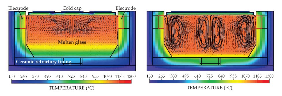
The reactions are governed by the substantial flows of heat and mass through the cold cap region, which can determine the glass formation rate. Historically, melters have relied on natural convection to produce mixing in the viscous glass pool. In melter bubbler technology, invented at the Catholic University of America’s Vitreous State Laboratory (VSL) in Washington, DC, in the early 1990s, gas bubbles rising from organized arrays of outlets transfer momentum to the molten glass. As shown in figure 1, the melter bubblers increase mixing and with it the rate of heat and mass transport to the reacting feed material in the cold cap. The result is an enormous boost in glass production rates, up to about a factor of five. The

Figure 1. Computer models of the Hanford Tank Waste Treatment and Immobilization Plant’s high-level waste melter without (left panel) and with (right panel) bubbling. The models include the effects of joule heating, viscous flows, and temperature-dependent materials properties. Black lines in the molten glass indicate glass flow vectors. The improved temperature homogeneity led to removal of a bottom electrode from the final design.
The first production-scale deployment of melter bubbler technology was in the M-Area melter at the SRS, which is the largest radioactive-waste melter ever operated in the US. The technology is also incorporated into all Hanford melters and was successfully retrofitted into the SRS Defense Waste Processing Facility melter in 2010 to double the melter throughput there. 13
Because the feed-to-glass conversion reactions occur at an interface, the maximum glass production rate scales approximately as the glass surface area, other things being equal. The first production-scale application of slurry-fed JHCM technology to HLW vitrification was the joint German–Belgian PAMELA facility, which operated in Mol, Belgium, from 1985 to 1991. That facility used a melter with a 0.72-m2 surface area. In the US, JHCMs have been used at the former reprocessing site at West Valley, New York, with a 2.2-m2 melter, and at two facilities at the SRS—one with a 2.6-m2 melter and the other a 5-m2 melter. Japan and India have also used JHCMs, and since the early 1990s China has been developing defense-HLW vitrification systems based on German JHCMs.
Vitrification facilities at Mayak in Russia have employed distinctly different JHCM designs, more closely resembling those used in commercial glass manufacturing, to produce sodium aluminophosphate glass from defense HLW. The Mayak melters are very large—about 10 m2—but achieve very low production rates because of the dilute feed, glass composition, and melter design; they have experienced several failures.
In France and the UK, where the vast majority of commercial spent fuel is reprocessed, the resulting HLW is vitrified using hot-wall induction melters consisting of an elliptical metal vessel. Glass is discharged by melting a frozen glass plug in a bottom drain. Bottom, versus side, discharge improves the removal of dense insoluble particles containing certain fission products such as ruthenium, rhodium, and palladium, which are more prevalent in commercial wastes. Induction heating is used, whereby a current is induced to flow in the wall of the melter. Consequently, the wall is the hottest part of the system, which limits melter lifetime to a few thousand hours due to metal corrosion and creep; in contrast, JHCMs can last five years or more.
To reduce the power demand, the hot-wall melter is fed with glass frit and waste that is first roasted in a rotary calciner to evaporate water and decompose nitrates. Because energy is supplied through a surface—the melter wall—to heat a volume, heat transport considerations limit the practical size of the melters. Higher throughput is therefore achieved by operating multiple melters in parallel. Six lines are installed at the La Hague facility in France, and three lines are installed at the Sellafield vitrification facility in the UK.
In 2010 one of the six lines at La Hague began operation with a 0.65-m-diameter cold crucible induction melter. Instead of a simple metal vessel, the walls are segmented, with vertical, water-cooled, metal strips sandwiched between dielectrics to prevent the flow of current around the circumference. The setup results in inductive coupling to the molten glass instead of to the wall. The cold wall freezes a layer of glass, which protects the wall from corrosion to increase lifetime and allow higher operating temperatures. The power profile from the wall decays exponentially with a penetration depth that varies inversely with the square root of the product of the power supply’s operating frequency and the electrical conductivity of the glass. Typical values of the penetration depth are a few centimeters at frequencies of a few hundred kilohertz. As a result, most of the power is dissipated close to the wall, and again limits the maximum practical size to about 1.4 m in diameter.
Treatment of Hanford waste
The waste stored in the Hanford tanks reflects the history of the development of reprocessing technology and the legacy of the extraction of about 67 tons of Pu. The chemical complexity and compositional diversity are vastly greater than in waste from modern, commercial fuel-reprocessing plants. Commercial waste is produced in a consistent and well-controlled process and has, by design, relatively little variation in chemistry. That difference in chemical complexity and the enormous disparity in the amounts and required processing rates make defense waste and commercial waste very different problems.
Unlike commercial-reprocessing waste, the acidic waste at Hanford was neutralized with sodium hydroxide to prevent corrosion of the carbon steel tanks used for storage. The roughly 50 000 metric tons of sodium that was added constitutes the majority of the solids in the waste. To illustrate the disparity in the magnitudes of the two waste treatment challenges, one hot-wall induction melter of the kind used at La Hague or Sellafield would take more than 3000 years to vitrify all the waste at Hanford. Obviously, a radically different approach is required.
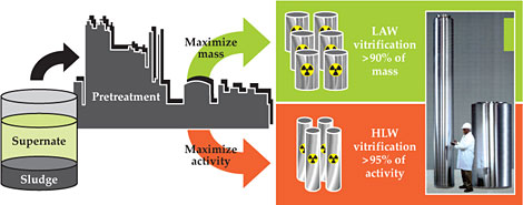
The vast majority of the atoms in the Hanford waste are not radioactive. The key is therefore to separate the waste into a large, cheaper-to-treat, low-activity waste (LAW) stream that contains most of the mass but as little as possible of the radioactivity and a much smaller HLW stream, which contains most of the radioactivity (see figure 2).

Figure 2. Waste storage tanks at Hanford contain a mix of radioactive sludge and a high-sodium salt solution called supernate. The waste will be separated into a low-activity waste (LAW) stream that contains most of the mass and a much smaller high-level waste (HLW) stream that contains most of the radioactivity. The photograph shows the two types of canisters that will be used to hold vitrified waste. The tall one on the left will hold about 3000 kg of HLW glass and the one on the right will hold about 6000 kg of LAW glass. Radiation levels at the surfaces of filled HLW and LAW canisters will be up to about 108 and 104 times greater than background, respectively. A level of 108 times background would provide a fatal dose in roughly three minutes. (Photo courtesy of the US Department of Energy.)
At West Valley and Savannah River, the LAW fraction is stabilized in a cement-based matrix and the HLW is vitrified. The Hanford Tank Waste Treatment and Immobilization Plant (WTP) that is under construction will vitrify both LAW and HLW fractions. Because disposal of treated LAW will be on site, stakeholders, including local community organizations and Indian tribes, have insisted on glass, which is more leach resistant than cement-based material.
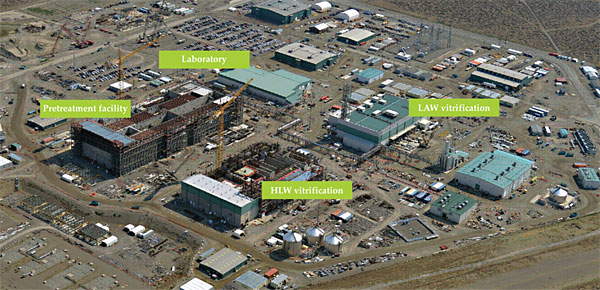
With two 10-m2 LAW melters and two 3.75-m2 HLW melters—all incorporating bubblers—the WTP will be by far the world’s largest nuclear waste vitrification facility. Shown in figure 3, the WTP consists of a pretreatment facility, which performs the separation, LAW and HLW vitrification facilities, a laboratory, and more than 20 supporting buildings.

Figure 3. Aerial view of the Hanford Tank Waste Treatment and Immobilization Plant (WTP) under construction. Once completed, the WTP will vitrify the approximately 210 000 m3 of mixed chemical and radioactive waste currently stored in underground tanks into separate low-activity waste (LAW) and high-level waste (HLW) glasses. (Photo courtesy of the US Department of Energy.)
Whereas facilities vitrifying commercial HLW can use an essentially fixed glass formulation, a wide envelope of formulations will be required at Hanford because of the diversity of waste compositions. Development of such formulations is a problem in constrained optimization. In a parameter space of several tens of composition variables, for a given waste composition and expected variability, glass formulations are sought that meet a range of properties determining product quality, compatibility with the melter design, and process economics.
The Hanford tanks contain varying amounts of HLW sludge, a residual high-sodium salt solution called supernate, and crystallized supernate called saltcake. The sludge, formed by precipitation of heavy metals and long-lived transuranics when the acidic waste was neutralized, is particularly complex, not only chemically but also with respect to mineralogy, particle size, and rheology. The major radionuclides in the supernate are those that are soluble at high pH, such as cesium and technetium. Prior to treatment, the saltcake must be redissolved and the sludge resuspended. The WTP pretreatment facility—12 stories tall and the size of four football fields—is designed to filter out the HLW solids from the supernate; remove cesium from the supernate by ion exchange; wash the solids to remove interstitial supernate; remove aluminum and chromium from the solids by caustic and oxidative leaching, respectively; and combine the ion- exchanged cesium with the solids for immobilization in HLW glass.
Breakthroughs in glass formulation have significantly reduced the need for several of those steps. For example, higher aluminum capacity in the HLW glass reduces the need for aluminum removal, and with it the amount of added sodium used for caustic leaching. In turn, the amount of LAW glass decreases. Similarly, higher chromium capacity reduces the need for chromium removal by oxidative leaching.
In view of the complexity of waste and glass compositions, often involving dozens of components, performance improvements through optimization of glass formulation are almost always possible. Such changes in glass and process chemistry have the tremendous advantage of being implementable without physical modifications to the facility or the equipment. Waste can be vitrified more efficiently by increasing the melt rate, the rate at which feed is converted to glass in the melter, and by packing more waste into the glass. A glass formulation optimization program that the VSL began for DOE in 2003 has already led to projected 30−50% reductions in the amount of glass and near doubling of melt rates; the compositional effects on melt rate are in addition to those provided by bubbling. 14
The improvements at Hanford have come through departures from more traditional nuclear waste glass formulations and have included lower-silica, higher-boron glasses and the addition of components such as vanadium, tin, zirconium, and zinc to increase sulfur incorporation and reduce glass leaching and refractory corrosion. Also, crystal formation in the melter, which can result in sedimentation and accumulation over time, is traditionally managed by formulating the glass so that the liquidus temperature is below the operating temperature. However, higher waste loading, the amount of waste packed into the glass, can be achieved by leveraging the increased tendency for suspension and entrainment afforded by bubbling to allow small amounts of crystal formation.
Costs and concerns
Unfortunately, treatment of Hanford tank waste has been plagued by false starts and cost and schedule overruns. An earlier privatized project was canceled due to cost escalations, but the WTP retained many aspects of the process and treatment technologies it had selected. The current WTP contract was awarded in late 2000 based on a projected cost of $4.3 billion and startup in 2007. In 2006 the cost was revised to $12.3 billion and startup was delayed to 2019, and further delays appear likely.
A 2012 Government Accountability Office report, which estimated the cost at $13.4 billion or more, identified the root cause of the cost increase as the decision to fast-track the project and start construction while design and testing was still in progress, 15 a risky strategy for such a complex first-of-a-kind project. Other contributing issues include the use of so-called black cells: enormous sealed concrete rooms that essentially require perfect reliability of equipment installed in them over the projected 40-year life of the facility.
Another concern is with the pulsed-jet mixers, which mix by alternately sucking and blowing fluid into and out of a submerged vessel by air pressure. Such mixers have never been used before for the kind of high-solids-content fluids found at Hanford, and test programs to determine their performance over the expected range of fluid rheologies have ballooned in both cost and duration. A key issue is whether the mixing is sufficiently effective to eliminate the potential for a criticality incident due to sedimentation and accumulation of Pu particles on the tank floor and to prevent the buildup of radiolytically generated hydrogen gas. There are also concerns relating to erosion and corrosion of materials. Most of the outstanding technical issues that have slowed progress on the WTP relate to the pretreatment facility; its construction has been halted while those issues are resolved.
Outlook
The need to remove and immobilize waste from the aging tanks at Hanford grows ever more pressing. To do so will require the completion, startup, and operation of what will be by far the world’s largest and most complex vitrification plant. Many challenges remain, but significant prospects exist for further enhancements in facility performance through continued improvements in glass formulations. Many vitrification plants continue to operate successfully around the world. The basic JHCM glass melter technology to be used in the WTP has a long track record and is underpinned by extensive testing on one-third-scale prototype pilot melter systems.
The biggest challenge is supplying feed to the WTP melters. The first step is the retrieval of waste from the underground storage tanks, a slow and complex process employing various vacuuming, sluicing, and washing technologies tailored to the particular physical characteristics of the waste. An ongoing program to reduce risk by transferring waste from single-shell tanks into double-shell tanks has completed 12 retrievals; up to 14 retrievals per year will be required to support full WTP operations.
The waste must then be separated into LAW and HLW fractions. However, it is possible that the pretreatment facility will never operate as designed, and perhaps not at all. Bypassing that facility is a potential solution that DOE officials are considering, 16 and various direct-feed approaches involving interim pretreatment systems are being developed; the cost of such systems has been estimated at $2 billion to $3 billion. 15
Other significant challenges include the very limited tank space—particularly as more tanks begin to leak—and the coupling of the HLW and LAW processes through their common feed from the tanks, which requires careful balancing to avoid costly idling of either the HLW or LAW facility.
Finally, unlike the other parts of the WTP, which were sized to complete treatment over roughly 30 years, the LAW facility was supposed to be one of two such plants, each with three melters. To cover the shortfall, various alternative supplemental treatment technologies have been considered; the state of Washington has consistently advocated for the longstanding vitrification plan, 17 but a decision has yet to be made.
Box. Vitreous State Laboratory
The Vitreous State Laboratory (VSL) at the Catholic University of America was established in 1968 as a center of excellence in glass science and technology with funding from the US Department of Defense. The VSL is home to the largest collection of test melters in the US based on Joule-heated ceramic melter technology. The largest is a one-third-scale pilot for the Hanford Tank Waste Treatment and Immobilization Plant’s (WTP’s) high-level waste (HLW) vitrification system. It also hosts what may be the largest and longest-running inventory of glass leach tests in existence—the inventory includes thousands of glasses, and the longest tests have been running for 36 years. The VSL has provided continuous support to the WTP since 1996 and developed the baseline and enhanced glass formulations and the majority of the glass property and vitrification system performance data that underpin both the low- activity waste (LAW) and HLW vitrification facilities.
Work at the VSL in the 1970s and 1980s on fiber optics led to the invention of very high surface area, nanoporous, glass-based ion-exchange materials for cleanup of contaminated waste water such as from nuclear reactors. A spin-off company called Duratek (now EnergySolutions) commercialized the materials, as well as later developments in vitrification technology, beginning a successful multidecade university–industry partnership that continues to this day. EnergySolutions designed both the HLW and LAW melters at Hanford.
The VSL performed melter testing and developed the glass formulation that was used at the West Valley Demonstration Project in New York to convert about 2300 m3 of HLW to 275 canisters of stable glass from 1999 to 2002. For the Duratek M-Area vitrification facility at the Savannah River Site (SRS), the VSL provided testing and onsite support and developed the glass formulations to vitrify about 2500 m3 of mixed LAW in the late 1990s. It continues to support ongoing efforts at the SRS to encapsulate HLW in glass and LAW in cement. The VSL has also provided glass-formulation and melter-testing support to the Japanese Rokkasho vitrification facility since 2005, performed vitrification testing for both high- and intermediate-level waste treatment at the Sellafield site in the UK, and in 2013 developed the cement formulation used to immobilize nuclear waste stored at the Separations Process Research Unit facility in Niskayuna, New York.
Current research at the VSL also includes cements, fly ash, geopolymers, single-molecule DNA biophysics, nanomaterials and devices, thermoelectrics, and spintronics.
Thanks are due to John Mather (NASA’s Goddard Space Flight Center) for suggesting this article. Support from the Department of Energy’s Office of Environmental Management and Office of River Protection is also gratefully acknowledged.
References
1. R. Rhodes, The Making of the Atomic Bomb, Simon & Schuster (1986).
2. R. S. Norris, H. M. Kristensen, Bull. At. Sci. 62(4), 64 (2006). https://doi.org/10.2968/062004017
3. W. Lutze, R. C. Ewing, Radioactive Waste Forms for the Future, North-Holland (1988).
4. I. W. Donald, B. L. Metcalfe, R. N. J. Taylor, J. Mater. Sci. 32, 5851 (1997). https://doi.org/10.1023/A:1018646507438
5. J. L. Crovisier, T. Advocat, J. L. Dussossoy, J. Nucl. Mater. 321, 91 (2003). https://doi.org/10.1016/S0022-3115(03)00206-X
6. R. E. Gephart, A Short History of Hanford Waste Generation, Storage, and Release, PNNL-13605 rev. 4, Pacific Northwest National Laboratory (October 2003).
7. W. J. F. Standring, Review of the Current Status and Operations at Mayak Production Association, Strålevern Rapport 2006:19, Norwegian Radiation Protection Authority (2006);
C. G. Sombret, A. Jouan, Analysis of Radioactive Waste Vitrification Practices in the Commonwealth of Independent States, EUR 16945, Office for Official Publications of the European Communities (1996).8. Blue Ribbon Commission on America’s Nuclear Future, Report to the Secretary of Energy (January 2012);
E. Bonano et al., Evaluation of Options for Permanent Geologic Disposal of Spent Nuclear Fuel and High-Level Radioactive Waste in Support of a Comprehensive National Nuclear Fuel Cycle Strategy, FCRD-UFD-2013-000371 rev. 1, Sandia National Laboratories (April 2014);
R. B. Stewart, Environ. Law Policy Annu. Rev. 40, ELR–10783 (2010).9. G. Aubert et al., Economic Assessment of Used Nuclear Fuel Management in the United States (rep. prepared for AREVA), Boston Consulting Group (2006);
M. Bunn et al., The Economics of Reprocessing vs. Direct Disposal of Spent Nuclear Fuel, Harvard University, Project on Managing the Atom (December 2003).10. R. Wigeland et al., Nuclear Fuel Cycle Evaluation and Screening—Final Report, FCRD-FCO-2014-000106, US Department of Energy (October 2014).
11. I. L. Pegg, I. Joseph, in Hazardous and Radioactive Waste Treatment Technologies Handbook, C. H. Oh, ed., CRC Press (2001), chap. 4.2.
12. C. C. Chapman, J. M. Pope, S. M. Barnes, J. Non-Cryst. Solids 84, 226 (1986). https://doi.org/10.1016/0022-3093(86)90781-7
13. J. N. Lindsay, Radwaste Solutions 18(2), 23 (2011). See also US Department of Energy Office of Environmental Management, EM Update 2(19), 3 (2010).
14. K. S. Matlack, I. L. Pegg, in Advances in Materials Science for Environmental and Energy Technologies II: Ceramic Transactions, Volume 241, J. Matyáš et al., eds., Wiley (2013), p. 47.
15. US Government Accountability Office, Hanford Waste Treatment Plant: DOE Needs to Take Action to Resolve Technical and Management Challenges, GAO-13-38 (December 2012).
16. US Department of Energy, Hanford Tank Waste Retrieval, Treatment, and Disposition Framework (September 2013).
17. US Department of Energy, Final Tank Closure and Waste Management Environmental Impact Statement for the Hanford Site, Richland, Washington, DOE/EIS-0391 (December 2012).
More about the authors
Ian Pegg is a professor of physics and director of the Vitreous State Laboratory at the Catholic University of America in Washington, DC.


