The Uranium Bomb, the Calutron, and the Space-Charge Problem
DOI: 10.1063/1.1995747
”Uranium! Uranium! Uranium!” A voice shouted out into the night from the second floor of a dormitory in Oak Ridge, Tennessee. It was 6 August 1945. That day, President Harry S Truman had announced to the world that the US had dropped a new weapon, a uranium bomb, on the city of Hiroshima, Japan. For years, those of us on the bomb project were cautioned not to say the word uranium, but now it was okay. There were code words and code letters for the things we worked with, and each of our new designs received a new name. The teletype messages that went back and forth between the radiation laboratory in Berkeley, California, and the Y-12 plant in Oak Ridge were total gibberish. The purpose of our effort was to separate “P,” or 235U from “Q,” or 238U. Those were easy to remember because P stood for precious and Q stood for qrap.
A few days later, another word burst on the scene with the issuance of the Smyth Report, the official government account of the history of the bomb project. 1 That word was “calutron.” Now that the device had achieved its objective, Ernest Lawrence wished to give recognition to the University of California by using the name calutron for the apparatus developed to separate P from Q. He had made an arrangement with report author Henry Smyth that the name be included, but never divulged the deal until the war was won.
The calutron’s separation method was based on electromagnetic mass spectrometry. (See
Cornell university
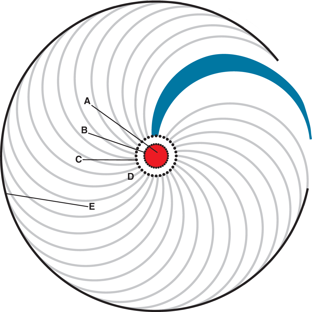
The calutron story starts around 1940 at Cornell University. Fellow student A. Theodore Forrester and I were finishing our graduate work under the direction of Lloyd P. Smith, who had obtained a contract to separate a quantity of lithium-6 for use in an experimental study of a new cancer therapy. Knowing about the space-charge problem and realizing he had to deal with only two fractions, 6Li and 7Li, Smith suggested trying a geometry, illustrated in Figure 1, similar to that of the electron magnetron. An arc ion source would be along the centerline parallel to the magnetic field, and ions would be accelerated radially outward. They would describe circular paths, and the fields would be adjusted so that the heavy fraction would collect near the 180° focus on a peripheral cylinder while the light fraction returned to be collected near the center. Smith reasoned that the symmetry would eliminate space-charge fields in the θ direction (in the usual cylindrical coordinates). Space-charge fields would have r and z components, and Smith had calculated how much ion current one would expect before the radial fields ruined the resolution in mass separation.

Figure 1. The radial magnetic separator at Cornell University was used to separate lithium isotopes. This cross section shows the relationship of its ion trajectories with those of the conventional Dempster mass spectrometer (blue area). Also shown are a circular arc (red area) struck from the cathode (A), short alternating sections of metal tubing and screen at ground potential (B), and matching sections of metal tubing and open mesh grid (C) at the accelerating potential. The location of the collector pocket for the lighter isotope is indicated (D), as is the focus where the heavier isotope collected (E). For ease of viewing, the elements A, B, and C have been somewhat enlarged.
The experimental apparatus was readied in the summer of 1941. Almost immediately, we observed clean resolution with higher currents than should have been possible. Shortly thereafter, we realized that we had stumbled onto a process wherein the ion beam automatically neutralizes itself by ionizing residual gas in the vacuum chamber. The positive ion beam presents a potential well to electrons. They are trapped while the ions they leave are immediately swept out along magnetic-field lines in the z direction. And the process is fast. Even when the accelerating voltage is swept at 60 Hz, the neutralization follows the beam location perfectly.
Furthermore, the process is self-limiting. Electrons accumulate while oscillating up and down along magnetic-field lines only until the potential well is filled. They move laterally with small cycloidal paths because of any residual space-charge fields perpendicular to the magnetic field. Collisions of the electrons with gas molecules cause the electrons to start new cycloids—fortunately always closer to the center of the beam. (See
We at Cornell didn’t know that at this very time, the Uranium Committee, an arm of the Office of Scientific Research and Development (OSRD) under Vannevar Bush, was negotiating with Smyth and Lawrence to start projects at Princeton University and the University of California. These would investigate whether space-charge effects might be overcome sufficiently to permit use of an electromagnetic method for quantity separation of 235U. Lawrence, who was in the process of building a giant 184-inch magnet at UC Berkeley, volunteered the use of it and the existing 37-inch cyclotron magnet. He would try the classic Dempster mass-spectrometer arrangement 2 and see how well he could do. Smyth proposed a time-of-flight method he called the isotron, invented by Robert R. Wilson. It used no magnetic fields, but employed a broad two-dimensional ion source to increase currents. Both of those projects were started in late 1941.
Word reached Lawrence of our work at Cornell. He contacted Smith and invited the three of us to join his project at Berkeley. Pearl Harbor had recently been attacked, and the country was at war. We felt a duty to go, although Smith would have to return within a few months. In mid-February we boarded a train in Ithaca and left the ice and snow for sunny California. From a railroad station on the way, we mailed a manuscript to Physical Review with the request that, because it should now be regarded as secret, its publication be postponed until the war was over. We wished to get credit for having discovered and explained the automatic self-neutralization of intense ion beams where there are no applied electric fields. Our manuscript was received on 18 February 1942 and published on 1 December 1947 after declassification. 3
The berkeley radiation laboratory
When we arrived at Berkeley, experiments were already under way in a small vacuum-chamber tank placed between the pole pieces of the 37-inch magnet. Also, there was arc-ion-source development using a smaller magnet from the cosmic-ray program. Getting sufficient ion current from the source was the greatest problem. By mid-March the ion currents were up and, for the first time, exceeded those possible without some space-charge neutralization.
The current above which resolution in mass separation is lost may readily be calculated from the divergence of the ions at the beam’s boundary, which is caused by the space-charge field there. In the Dempster spectrometer, the beam is accelerated at the ion source from a narrow slit that is long in the direction of the magnetic field. The beam takes the shape of a double-bladed wedge bent into a semicircle, and comes close to focusing at the 180° point. If the space-charge field widens the focus even further, until the additional width is equal to the separation distance of the two isotopes being separated, then the useful beam current limit has been reached. The current I of the desired isotope in milliamps per centimeter of height of beam in the magnetic-field direction is 3
where η is the fractional abundance of the desired isotope, A 1 and A 2 are the atomic weights of the two isotopes being separated, V is the accelerating voltage, and H is the magnetic field in gauss.
For separating 235U from 238U, the maximum I of 235U is 4 × 10⁻⁵ mA/cm for a voltage of 35 kV and a magnetic field of 3500 gauss. With that current, it would take more than 5 years to accumulate 1 kg of 235U with 1000 separator units having beams 60 cm in height and operating at full capacity without interruption. That was considered unachievable, so our challenge was to see how much beam current might be increased above the space-charge limit.
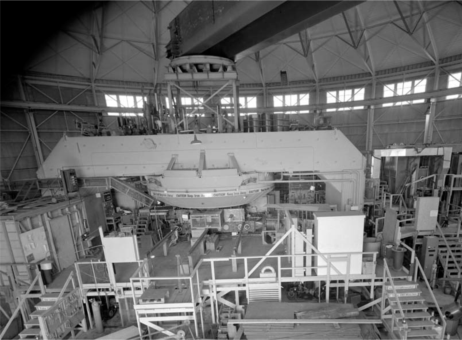
A significant change took place in the beginning of June 1942: The giant 184-inch magnet on the hill behind the campus became ready for operation (see Figure 2). Smith had returned to Cornell. More and more of Lawrence’s former students were arriving to join the effort. The center of activities moved to the 184-inch magnet building, although work continued at the old radiation lab building and at others on the campus. Robert Oppenheimer’s theoretical group, which was assisting us, operated from the physics building, Le Conte Hall.

Figure 2. The 184-inch magnet at the University of California, Berkeley. The gap between the 184-inch diameter pole pieces is 72 inches.
The photo, courtesy of the Lawrence Berkeley National Laboratory Image Library, is from 1943.
Electromagnetic mass spectrometry
Despite their varied geometries and field combinations, mass spectrometers incorporate two steps, each of which filters ions of similar energy, momentum, or velocity. In each step, the trajectories are completely determined by the physical parameters of the apparatus along with the mass, charge, and velocity of the ion. For example, an energy filter can be a simple acceleration of the ion with charge e and mass m through a potential difference V. By equating the energy gained through that acceleration with the ion’s kinetic energy, one obtains mv 2/2 = eV, where v is the ion’s velocity.
A magnetic field H perpendicular to the path of the ion provides a momentum filter. The ion subjected to such a field will describe a circular path of radius r. After equating centripetal and magnetic forces, one obtains the momentum expression mv = Her.
A velocity filter can use crossed electric and magnetic fields. In a simplest case, the electric field E and magnetic field H are perpendicular and the ion moves in a straight line orthogonal to both fields. Equating the electric and magnetic forces determines that v = E/H.
From any two of the three equations, velocity can be eliminated as a variable. Thus, using two mass-spectrometer steps allows a discrete solution for mass, which effectively results in spatial separation of different isotopes.
For some mass spectrometers, the electric field varies in time. Such time-of-flight spectrometers typically use a fixed-potential accelerating electric field as an energy filter, followed by a velocity filter that uses an RF electric field. No magnetic field is necessary.
A Dempster-type mass spectrometer 2 uses the fixed-potential energy filter, followed by a semicircular path in a uniform magnetic field as a momentum filter. The calutron developed during World War II modified that basic arrangement to increase ion currents while still retaining adequate resolution in mass separation.
Big-time physics
The large circular building that housed the giant magnet was ideal for our purposes. Around its wall on the inside were numerous shops and batches of heavy electrical equipment. An upper level included offices and conference rooms. In the center was the big magnet with a hastily erected platform at the level of the lower pole-piece surface. Two large vacuum-chamber tanks with slightly over 2 feet of inside clearance in the magnetic-field direction were stacked in the 72-inch gap. They had access faces on opposite sides for mounting ion sources and collectors. Control rooms for each tank were nearby at platform level.
Crews for each tank worked around the clock in three shifts. Much of the work was done inside the magnet gap with the magnet turned on. We all knew not to wear a watch or carry keys. The nails in our shoes were no problem, but they made walking seem as though we were working in a muddy field. We had nonmagnetic tools made from a beryllium–copper alloy. Occasionally, a nail or other ferrous object would get loose and come flying like a bullet to the lip of the pole piece. After a couple of accidents, we learned that the liquid-nitrogen-containing Dewar flasks, which were in large metal canisters on casters, needed to be chained to the railing at the edge of the platform. A sofa was placed on top of the magnet where anyone detained for an extended run could catch a nap. Also, it was the warmest location in the building on a foggy night.
One immediate need was for experts in high-power-circuit design. Lawrence contacted movie studios in Hollywood. They were looking for work and immediately sent a very competent team that stayed through our entire project. Marcus Oliphant, who had come to the US from England, arranged for a group of superb physicists to come from that war-torn nation. Both Oliphant and Harrie Massey, who also came, were subsequently knighted by the queen. The General Electric Research Labs sent a good group headed by Kenneth Kingdon. Westinghouse sent a team led by William Shoup, who was joined later by Edward U. Condon. Lots was happening; everybody was cooperating and one could feel the excitement. We were like a swarm of bees in a building that even looked like a hive!
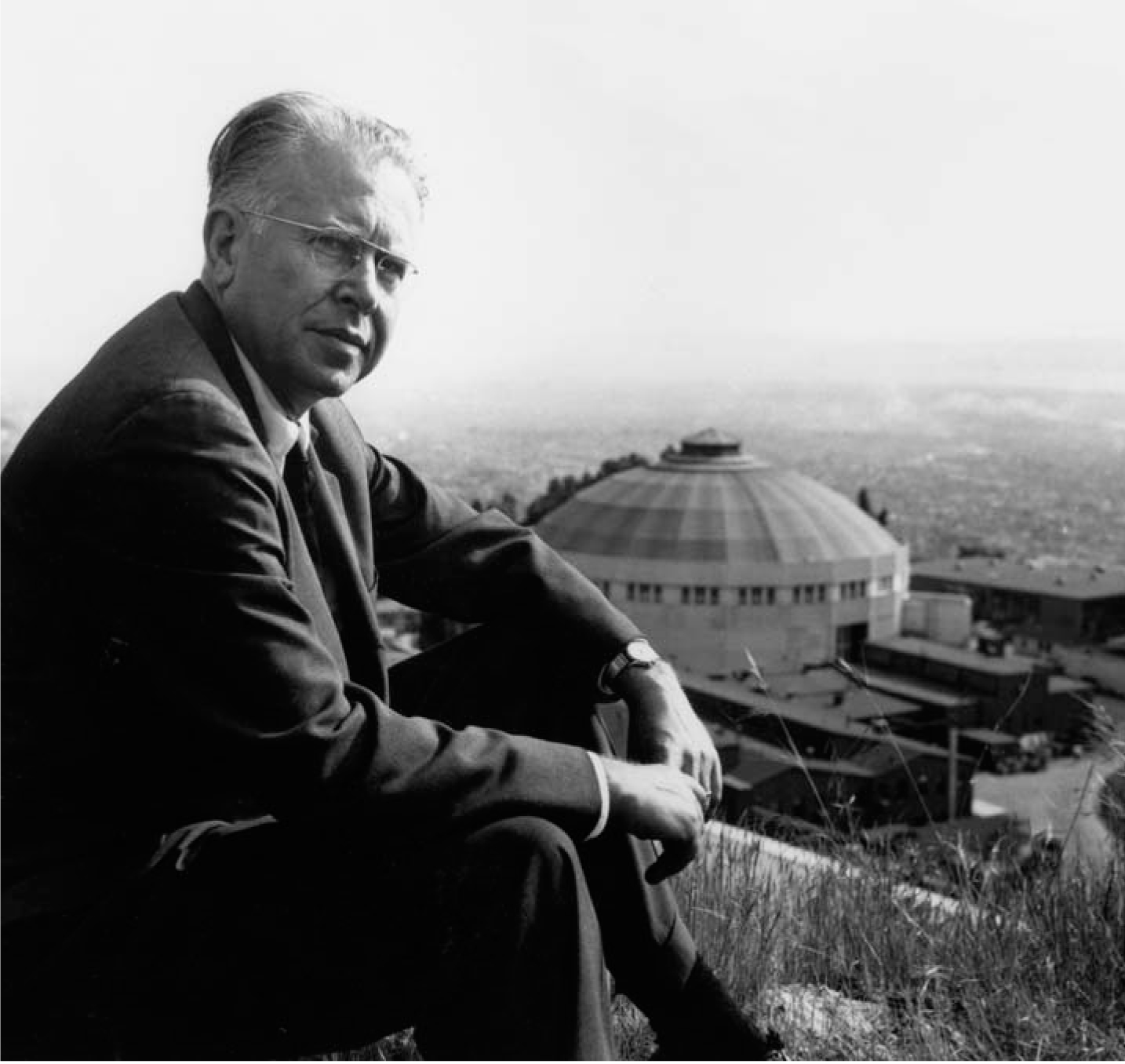
But there was no question as to who had the role of queen bee. It was, as we all called him, E.O.L. But to his face, it was always Ernest. Lawrence, seen in Figure 3, was a big man with strong hands, a healthy boyish complexion, a ready smile, and a big shock of hair. But most impressive were those penetrating bluish eyes. Nobody worked harder or had more enthusiasm than Lawrence, and his approach was perfect for the kind of development being done. He believed in thinking a little and experimenting a lot. There were so many variables and we left none uncovered. I can’t begin to explain all of the interesting avenues our work explored. But I must mention one that had critical consequences.

Figure 3. Ernest Lawrence as he poses on the big hill behind the University of California, Berkeley, campus. The 184-inch magnet, housed in the building visible in the background, became operational in June 1942, about the time this picture was taken.
(Courtesy of the Emilio Segrè Visual Archives, Physics Today Collection.)
On the matter of neutralization of the space charge, no means of introducing electrons into the beam worked better than simply depending on the beam to ionize the residual gas in the tank. But the pressure had to be about 2 × 10⁻⁵ torr. Half of that and the beam became unstable, especially with sparking. Unfortunately, we were trying to separate a lighter isotope from a much more abundant heavier one, 238U. Scattering of the beam by residual gas caused the heavier ions to reduce energy and radius, and to enter the collector intended for the 235U, thereby reducing the enrichment obtained. We knew this, because experiments decelerating the collected ions to near zero energy improved the enrichment. But such a collector reduced the final currents too much.
A compromise had to be struck, and reluctantly the decision was made to go to a two-stage process to achieve enrichments necessary for the bomb design. The stages would be called the alpha and beta. In the beta stage, there would be the new problem of chemical recovery of all uranium used because beta-stage feed material would be so valuable.
The atomic bomb project was now being taken very seriously. The Manhattan District of the US Army Corps of Engineers, under the command of Major General Leslie R. Groves, had been brought in to take charge. It had already set up the Los Alamos weapons lab in New Mexico. The isotron project at Princeton was shut down for lack of any positive results. Key personnel from there, including Wilson and Richard Feynman, went to Los Alamos. The project at Berkeley was transferred from OSRD to the US Army on 1 May 1943. A short time later came the surprising news that a plant for its process would be built in eastern Tennessee, where there was access to power from the Tennessee Valley Authority.
The calutron
The electromagnetic isotope separator design developed at Berkeley was a variation of the Dempster mass spectrometer. Did it really deserve the name calutron, which advertised the university? I believe it did, because of four important new features that contributed to increased throughput and resolution. These are features other than the use of extremely high accelerating voltages.
The first new feature was the use of magnetic shims. As designed by Oppenheimer’s theoretical group, the shims employed two shaped iron sheets approximately 3 feet wide and extending all the way across the tank, as viewed from the ion source. They were bolted to the top and bottom surfaces in the tank’s central region. Their purpose was to slightly increase the magnetic field. That preferentially, if only very slightly, decreased the radii of the trajectories of ions exiting the ion source with small divergence, and brought those ions to a focus at the collector together with the ions of wider divergence. In effect, the altered magnetic field produced better resolution with wider angular divergence from the source, which improved both throughput and resolution. A disadvantage was that the focus at the collector was an odd-shaped nonplanar curve instead of a straight line.
Lawrence wanted to alleviate the problem with so-called fish shims that would be anchored at midplane like a flat fish. To Lawrence’s great disappointment, Groves said “No,” and that was that. Groves felt the urgency and wisely foresaw new problems. But he had the greatest admiration for Lawrence, whom he considered a national treasure. He even refused to allow Lawrence to fly, and required him only to travel by train.
The second calutron innovation was the use of multiple beams. Several arc ion sources were located a few inches apart on a line perpendicular to the initial direction of the accelerated beam. Of course, multiple collecting pockets had to be provided at the 180° focus. In traversing from source to collector, the beams had to cross, and at first their mutual interference caused great trouble. Hans Bethe, who was visiting at the time, quipped, “Lawrence expected multiplication, but he got division.” With further experimentation, we eventually learned the conditions for stable operation with multiple beams. Production designs incorporated either two or four beams per tank.
Other features
Up until that time, the ion source had been operated at ground potential and the accelerating slit at high negative voltage. That required the collectors to be at high negative voltage and to have a metallic tank liner at the high negative. The liner was a constant problem, and it reduced the usable beam height. The next major innovation was to eliminate the high-voltage liner, put the collectors at ground potential, and operate the source at high positive voltage. But that created a monstrous problem: The tank was at ground potential, so the region around the source had exactly the conditions for the classic Phillips discharge—magnetic field extending between negative end plates and an electrode maintaining a positive region in between.
The region immediately surrounding the source presented a positive-potential well to electrons, and trapped them much as the ion beam did. But in this case, the applied field was one the electrons could not neutralize. And now the electrons could have many thousands of volts of energy, depending on where they were created by ionization. At the residual pressure around the source, the electron current oscillating up and down the magnetic-field lines could multiply exponentially into an avalanche that would destroy any positive electrode surface that finally collected it. Holes were melted through quarter-inch-thick tungsten plate.
The solution, while hard to describe, was truly ingenious. A grounded and fitted shield, with plenty of perforated holes to allow for vacuum pumping, was installed to closely surround the big source block. The shield had oblong bulges called blisters that were each several inches long and that enclosed fins—short lengths of copper-plate strips brazed to the source block. Two overlapping sequences of fins and blisters just above and below the midplane perpendicular to the magnetic field reduced the distance in which the trapped electrons could oscillate from about 2 feet within the tank to about 2 inches within the blister. Furthermore, as the electrons traveled laterally within the blister, they executed cycloids in the direction of E × H. Then, as they went around the end of a fin, they would see, along magnetic-field lines, the overlapping fin in the other plane and be collected. That arrangement prevented wasteful electron drain currents from building up, and it worked!
The fourth major feature of the calutron was the so-called accel–decel. The positive source now made it possible to interpose a high negative accelerating slit between the ion source slit and the final slit at ground potential. The ions would first be accelerated by, for example, 70 kV, and then decelerated by 35 kV to follow trajectories at 35 kV in the grounded tank. The very high initial voltage allowed us to extract higher ion currents. But because of the deceleration step, one could retain the same radius of trajectory in the tank without increasing the magnetic field.
The large amount of electrical equipment at high voltage presented our greatest hazard. We took care to use circuit interlocks on gates and cages. Those were essentially switches that, when opened, prevented the high voltage from being turned on. Fortunately no one was electrocuted, although in the frenzy of work, there were a few close calls. I was one of those, and I owe my life since that day to a scream by a quick-thinking Frank Oppenheimer.
The ion sources, except for their large scale, were more conventional. Each was a full-length arc struck between a replaceable, large-gauge tantalum wire filament and a graphite box enclosing the arc. The heavy source block, supported on porcelain bushings, had heaters that warmed a large reservoir of uranium tetrachloride. Careful temperature regulation ensured optimum vapor pressure in the boxes. Willard Libby, later of carbon-14 fame, came from the gaseous diffusion project at Columbia University to acquaint us with the tricks of using uranium hexafluoride. That compound had the advantage of being a gas at room temperature and would have been easier to use. In the end, UF6 was rejected because of a much reduced lifetime for the arc filament and its collimating slot.
In late 1943, the production design of what was called Alpha-I had to be frozen before development work on the high-positive source and accel–decel had been completed. Those features would later be incorporated into the Alpha-II design. The plant in Oak Ridge was coming together. The first team to go there had the assignment of mapping the magnetic fields. Others for plant start-up would soon be following.
The Y-12 plant
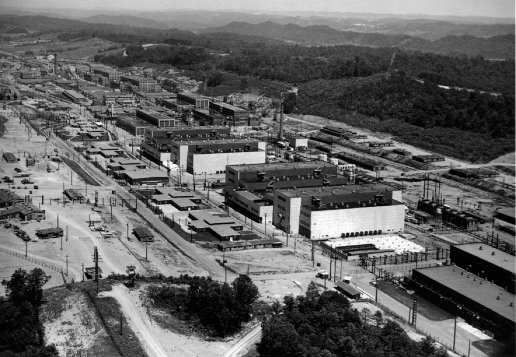
The US Army Corps of Engineers had created a town in the mud of the Tennessee hills west of Knoxville. In adjacent valleys, army contractors were building plants for the Manhattan Project. Ours was the Y-12 plant (see Figure 4), which eventually included nine large production buildings. Each building contained one or two racetrack-shaped assemblies such as the Alpha-I track shown in Figure 5. The racetracks alternated tanks, set on edge, with magnet excitation windings. Copper was scarce, and the US Treasury Department loaned 15 000 tons of silver for the windings. As many as 96 gaps for tanks were designed into a single racetrack. It was staggering!

Figure 5. This Alpha-I racetrack was part of the Y-12 plant in Oak Ridge, Tennessee. In it, process tanks with calutron units alternate with magnetic windings made of silver. Electrical-equipment cubicles with control panels are in a separate bay. Vacuum pumps are on a lower level.
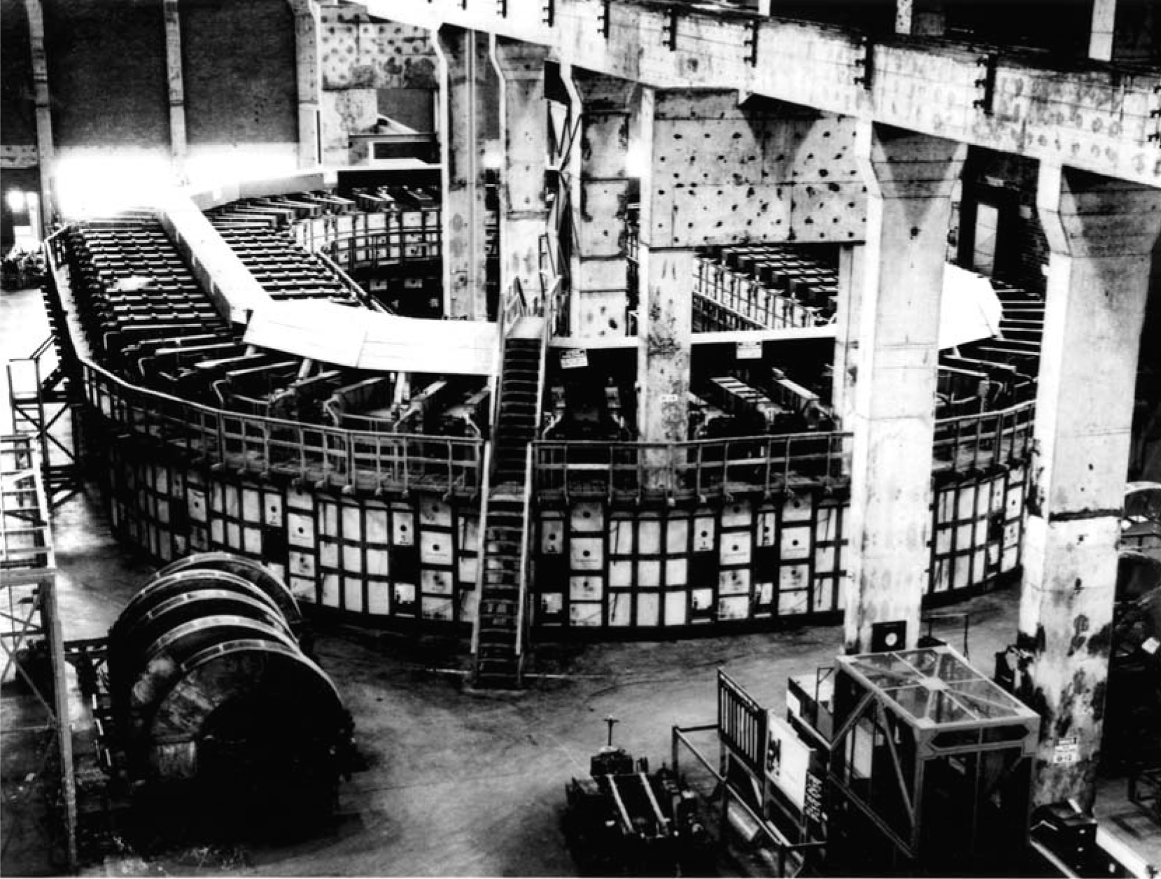

Figure 4. The Y-12 plant in Oak Ridge, Tennessee, was a part of the Manhattan Project. The site included nine production buildings and was dedicated to electromagnetically separating uranium-235 from uranium-238.
(Courtesy of Oak Ridge National Laboratory.)
Big industry had been called in. The engineer–constructor was Stone and Webster of Boston; the racetracks and their large generators were built by Allis Chalmers; Westinghouse made the internals, sources, and collectors; General Electric handled the electrical cubicles; and the operating company was set up as a division of Eastman Kodak called Tennessee Eastman.
The first track to go into operation, in early 1944, was the Alpha-I. It had shims, two beams per tank, a grounded source, and no accel–decel. Its performance was not nearly as good as that of the Alpha-II, which followed. Alpha-II had shims, four beams, a high-positive source, and accel–decel. The Beta tracks that followed next were like Alpha-II, except parameters were halved—two beams, 2-foot-radius paths instead of 4-foot, and a beam height of 7.5 inches instead of 16. The magnetic field for the Beta tracks had to be doubled to between 6000 and 7000 G. And the Beta tanks required a water-cooled stainless steel liner for the chemical recovery of all uranium that did not reach the collector pockets.
The design of all of this equipment was based on results from experimental apparatus at Berkeley. The rush to get into production omitted any pilot-plant phase, and many serious start-up problems resulted. 4 The magnet coils in the first Alpha-I track had shorts to ground from rust and sediments in the cooling oil. A four-month delay ensued while all of the silver coils from that track were shipped back to the Allis Chalmers plant in Milwaukee, Wisconsin, for cleaning and other corrective measures.
Alpha-II suffered devastating failures of the large insulating bushings supporting the source block. Operations were hampered for months until we obtained bushings made from improved porcelain. Even the chemical recovery of enriched uranium was initially so poor that it threatened the viability of the overall project. These and other difficulties were overcome one by one, as Lawrence steadily maintained his unflagging optimism and drive.
One of the best beam diagnostic techniques was simply to look. Through a window with protective shutter built into the tank wall, one could easily see the beam floating like a pale blue 3D ghost. Depending on conditions, ionized chlorine or Cl2, ionized combinations of U and Cl, and even doubly ionized U might be visible. And in the Beta tank, one could actually see the beam of 235U, although it was approximately 10% of the total U current.
The calutron was a temperamental piece of equipment. Each unit was operated from a control panel at the front of a cubicle containing the electrical equipment. The operators were mostly young women scoured from the back country of Tennessee. Many were uncomfortable having to wear shoes, and their drawl was often hard to understand. But when it came to patience, no one was their superior. And the calutron required patience. With no scientific understanding, those women became much better operators than our lab personnel from Berkeley.
As many as 22 000 nonscientist employees worked at Y-12. 5 What did they think we were doing? The plant had no receiving dock and no loading dock. Nothing went in or out, but everybody was very busy. For a time, they were given a cock-and-bull story about broadcasting radio signals that jammed the communications of our enemies in Europe and the Pacific. But it was wartime, and people accepted the fact that our work, whatever its purpose, must be important.
Late in 1944, a fortunate change boosted the throughput and final 235U enrichment from Y-12: Low-enrichment feed material from Oak Ridge’s thermal diffusion plant became available. Its output, obtained independently of the Y-12 effort, was introduced at a time when Y-12 was at its full capacity of 1152 tanks. A big push was mounted around the beginning of 1945 that led, within a few months, to the accumulation of the necessary enriched uranium, and to Truman’s announcement of 6 August.
Just three years earlier, our challenge had been to see how much we could exceed the limit set by the space-charge effect on ion beam currents. Now we knew. A good run on an Alpha-II unit would last 7 to 10 days and was usually terminated when the graphite facing on the 238U collector pocket had been sputtered away. During that time, the total charge measured to the 238U collector would be in the neighborhood of 15 A·h per beam. If averaged over a one-week period, that amounts to a beam current approximately 400 times the calculated space-charge limit!
Space-charge neutralization
Since the time of Charles Darwin, discovery of simple, effective, and beneficial biological processes has not been a surprise—they all have had the slow guiding hand of evolution. But it is extremely rare to discover such a process in the physical world. Instead, society undertakes to bend nature to serve its technological needs. Automatic self-neutralization of ion beams is a wonderful solution to the problem of space-charge repulsion, and it occurs totally without human intervention.
With some form of Dempster mass spectrometer, all that is required is a low pressure of residual gas in the vacuum chamber to permit ionization by the ion beam itself. Scattering of ions by that gas reduces the enrichment of separated isotopes, but a broad window of operating conditions makes possible essentially 100% neutralization and reasonably high enrichment factors.
With the Alpha-II calutron operation, about 10% of the beam ions traversing from source to collector cause ionization. Given their transit time, the beam would be neutralized in a few milliseconds. There is then continuing production of trapped electrons; those having a little more momentum in the direction of the magnetic field are constantly replaced by electrons of lower energy. With any interruption of beam current, the electrons would be swept out in microseconds.
Discovered
3
in 1941, beam neutralization
▸ is established in all beam regions at a rate independent of the beam current in the region,
▸ can follow fluctuations in beam location and intensity at frequencies up to about 1 kHz,
▸ appears to be 100% effective with steady beams, and
▸ places no limit on total beam current.
The process is a gift from Nature and, in contrast to those in the biological world, is one of a small number of beneficial natural physical processes. It has made possible the quantity separation of isotopes of elements throughout the periodic table for use in science, technology, and medicine.
The legacy
The electromagnetic separation of 235U could not have taken place without our having overcome the space-charge limitation. We at Cornell and, later, Lawrence at the University of California independently suggested using a Dempster-type instrument—the only basic electromagnetic method of isotope separation that offers a solution. Its elements are an accelerating-potential-based energy filter in which space-charge fields are unimportant, followed by a momentum filter consisting of a drift space in a magnetic field, where no applied electric fields exist and where space charge can be neutralized by trapped electrons. No other combination of steady electric and magnetic fields has that capability.
During World War II, the Germans gave up any attempt to separate 235U electromagnetically because they did not consider the space-charge problem soluble. 6 The Japanese also considered the electromagnetic method, but gave up on it for the same reason. 7,8
We at Cornell were the first to observe and explain the ion beam neutralization process. Our article, withheld from publication for more than five years, was titled “On the Separation of Isotopes in Quantity by Electromagnetic Means.” That, of course, was the purpose of the calutron project that came later and produced the Hiroshima bomb material. But the bomb has not been the project’s most important legacy. Other methods were being used to make bomb material. A plutonium bomb was dropped over Nagasaki, Japan, three days after Hiroshima was bombed, and the gaseous diffusion plant was coming on line. It would produce enriched uranium at a much faster rate and lower cost.
The most important legacy of the project has been the contribution to science, technology, and medicine made possible through the use of separated isotopes of nearly all the elements of the periodic table. Hundreds of kilograms have been prepared for research and diagnostics in physics, chemistry, Earth sciences, biology, and medicine. This service has been provided at cost for almost 60 years through the use of calutrons in the pilot units and Beta tracks at Y-12, all operated by Oak Ridge National Laboratory. Nationally and internationally, thousands of customers and millions of medical patients have benefited. 9
The development and use of the calutron to produce enriched uranium for the first atomic bomb that was exploded in warfare, and then to produce the full spectrum of separated isotopes for uses in peacetime, is the greatest example of beating swords into plowshares in the history of humankind. For its contribution in both wartime and peacetime, the physics profession can be proud.
References
1. H. D. Smyth, Atomic Energy for Military Purposes, Princeton U. Press, Princeton, NJ (1948).
2. A. J. Dempster, Phys. Rev. 11, 316 (1918) https://doi.org/10.1103/PhysRev.11.316 .
3. L. P. Smith, W. E. Parkins, A. T. Forrester, Phys. Rev. 72, 989 (1947) https://doi.org/10.1103/PhysRev.72.989 .
4. R. G. Hewlett, O. E. Anderson, A History of the United States Atomic Energy Commission, vol. 1, Pennsylvania State U. Press, University Park (1962).
5. C. W. Johnson, C. O. Jackson, City Behind a Fence: Oak Ridge, Tennessee, 1942–1946, U. of Tennessee Press, Knoxville (1981).
6. D. Irving, The German Atomic Bomb, Simon and Schuster, New York (1967).
7. F. H. Schmidt, Science 199, 1286 (1978) https://doi.org/10.1126/science.199.4335.1286-c .
8. W. E. Parkins, Science 200, 255 (1978) https://doi.org/10.1126/science.200.4339.255 .
9. L. O. Love, Science 182, 343 (1973) https://doi.org/10.1126/science.182.4110.343 .
More about the authors
Bill Parkins retired from Rockwell International, where he was director of research and technology for the energy systems group. He now lives in Woodland Hills, California.
William E. Parkins, Rockwell International, Research and Technology for the Energy Systems Group, US .


