The Physics of Intensity-Modulated Radiation Therapy
DOI: 10.1063/1.1522214
Cancer does not come in shapes that are easy to treat. Tumors extend into surrounding cavities and shove aside healthy organs. They march along routes of blood vessels and creep between muscles, growing into complex three-dimensional shapes. Frequently, normal structures find themselves flanked by malignant cohorts. As described in the introductory article on page 34, selective irradiation of the 3D volume of a malignant cancer is the goal of radiation therapy. The challenge is to deliver a sufficiently fatal dose of radiation to the target volume while minimizing the damage to surrounding normal tissue.
About half of all cancer patients receive radiation therapy, often in combination with other treatments. The most common form of radiotherapy, irradiation with high-energy x rays, has for five decades used multiple exposure angles to build up the dose delivered to the target without excessively exposing the healthy tissue in the vicinity of the target. Today, such exposures are achieved by placing the patient on a table at the center of a rotatable gantry, shown in figure 1, that delivers the x rays. The aperture of the x-ray beam is shaped to the outline of the tumor volume. The aperture is then expanded by a margin to account for uncertainties in the tumor location and in the positioning of the patient for each daily treatment.

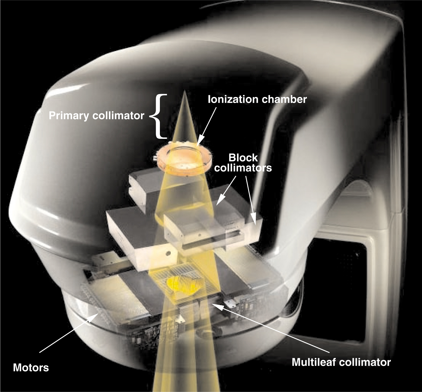
X-ray beam shaping. Within the gantry assembly (gray), brehmsstrahlung x rays produced by high-energy electrons incident on a tungsten target are restricted to a cone by the primary collimator, the shielding around the target, and the bending magnet. An ionization chamber immediately below the primary collimator produces current that is integrated and digitized to control the treatments. Motorized block collimators reduce the field to a rectangle that circumscribes the irradiation area. The leaves of the multileaf collimator (located about 50 cm below the tungsten target) are positioned by individual motors controlled by a digital system to fine-tune the shape of the field.
© 2002 VARIAN MEDICAL SYSTEMS
The careful shaping of apertures to match the 3D shape of the target has come to be known as 3D conformal radiotherapy (3DCRT). Implementing 3DCRT has required new technology that can shape fields efficiently. That technology, computer-controlled multileaf collimators (MLCs), has in the past 10 years opened the door for new techniques that offer improved control over the dose delivery.
To protect normal structures selectively and to produce concave dose distributions, the x-ray intensity within the projections of the target volume must be modulated. In the mid-1990s, several research groups began to investigate MLCs that provided not just static control of the beam aperture shape, but also dynamic control of aperture sequences that can be used to spatially modulate the x-ray beam intensity. Using this technique, termed intensity-modulated radiation therapy (IMRT), the delivered dose can be tailored to fit inside the 3D surface that encloses the target volume, while sparing nearby sensitive tissues. 1 With the careful control it enables, IMRT has attracted significant attention in research labs and clinical settings, and also from vendors of radiation oncology equipment and software. IMRT has been available at major therapy centers for the past five years and is rapidly spreading into regional and local radiotherapy facilities.2
Shaping the beam
MLCs allow the quick and controllable adjustment of an aperture to shape the x-ray beam used to irradiate the target volume. Figure 1 illustrates a typical collimation system on a medical linac, in which an MLC serves as the last collimation stage. Different vendors have elected to use different collimation configurations, but the results are essentially the same.
In the setup of figure 1, x rays are produced when electrons, accelerated in a resonant-cavity waveguide to energies of 4–25 MeV, strike a water-cooled tungsten target. The collimation system then shapes the resulting x-ray field in three stages. First, a fixed primary collimator attenuates all but the forward-directed bremsstrahlung cone. Before the second collimation stage, the cone of radiation passes through a sealed, parallel-plate transmission ionization chamber. The resulting ionization current is digitized and used to monitor and control the radiation sequence. The beam next passes through a set of motorized tungsten blocks that reduce the circular cross section of the cone to a rectangular field circumscribing the desired field shape. Finally, the individual leaves of the MLC are set to the boundaries of the desired field shape.
As shown in figure 2, the MLC consists of up to 120 leaves arranged as opposed pairs. Each leaf is a tungsten plate about 2.5 mm wide and 10 cm thick, which attenuates the x rays by a factor of about 100. The sides of each leaf dovetail with neighboring leaves to reduce leakage. Small electric motors move the individual leaves in and out of the beam along adjacent tracks. Due to the divergence of the x-ray beam, the size of the aperture formed by the leaves must be about half the size of the field shape at the patient.

Multileaf collimator, showing the interlocking pairs of leaves that are slid back and forth by motors (housed on the right) to define the beam aperture.
© 2002 VARIAN MEDICAL SYSTEMS
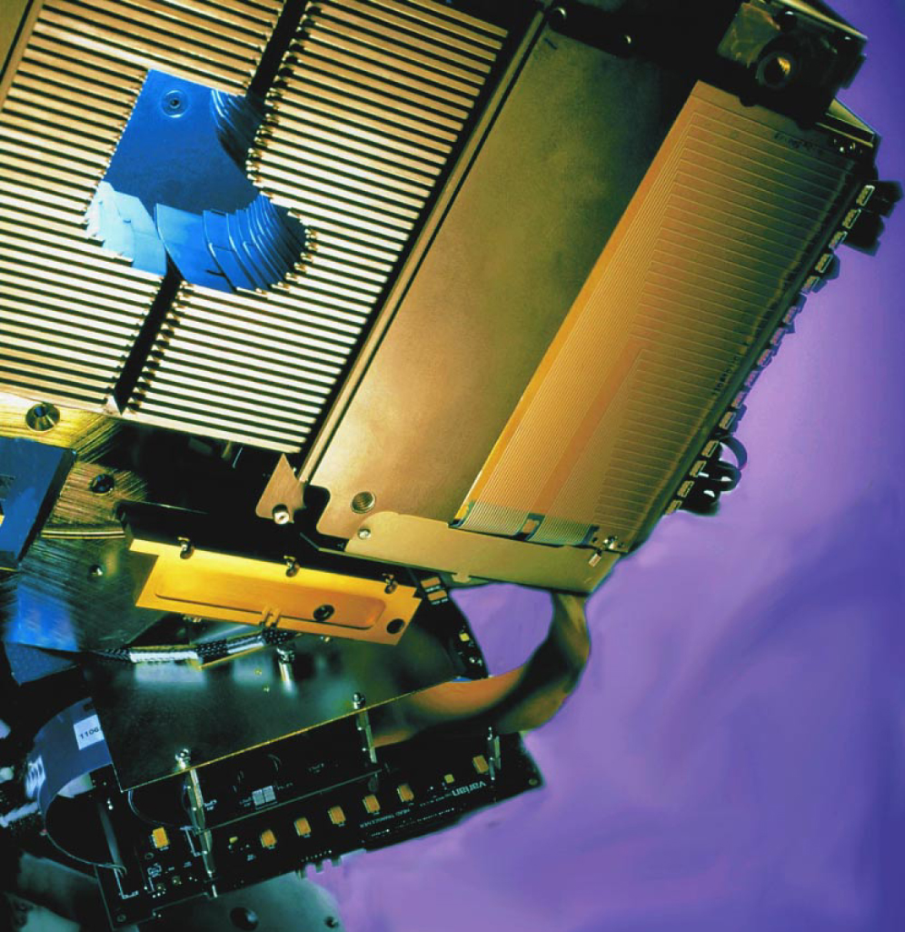
The position of a leaf is determined precisely by electronic and electrooptical position encoders that are integrated with the leaf motors into a digital control system. This system provides fast and accurate real-time control of the leaf positions. What is more, the electromechanical control of the leaf positions and the angle of the beam direction (that is, the gantry angle) can be coordinated with the dose measurements from the transmission ionization chamber. Thus, a sequence of apertures can be synchronized with the dose delivery, with a time resolution of about a dozen milliseconds.
The control system allows dose delivery in increments through a sequence of aperture shapes at one or more specified gantry angles. Such a degree of control of dose delivery has made possible the implementation of 3DCRT. In addition, the system can interpolate the leaf positions linearly from one gantry angle to the next—or even during the exposure at a given gantry angle. That additional level of dynamic control has opened the door to IMRT.
Optimizing the beam intensity
The idea behind IMRT is straightforward: When five or more exposure angles, each at a different fixed gantry position, are used to deliver a treatment, the target volume is crossed redundantly by x rays from the multiple directions. With that redundancy comes flexibility. The dose delivered by a field coming from one direction can be reduced within part of its aperture to spare a structure or to shape the dose distribution. The resulting dose inhomogeneity—a streak of low dose across the target volume—can be compensated for by increasing the intensity within portions of the apertures from other directions. Many versions of IMRT have been developed, all of which consist of two basic components: inverse treatment planning (to determine the intensity patterns to be delivered from each direction) and treatment delivery (to determine sequences of apertures shaped by MLCs to create the intensity patterns).
IMRT presents a classic example of an inverse problem: What intensity patterns are needed at the various exposure angles to generate a desired dose distribution? The mathematics are conceptually the inverse of computed tomography calculations: To reconstruct CT scans, two-dimensional x-ray transmission data are processed to extract a three-dimensional image (see the article by William Hendee, Physics Today, November 1995, page 51 ); with IMRT, the desired 3D dose image is the input, and 2D maps of the incident fluence at the various exposure angles are the output. Allan Cormack, who received the 1979 Nobel Prize for the invention of CT, investigated this problem early on,3 among others.4
The mathematical inversion technique has a problem, however: For all practical clinical cases, the direct inversion gives answers that require negative intensities, or sometimes imaginary intensities. So a more practical alternative has been adopted: Iterative search algorithms are used to select the intensity patterns that optimize a computed dose distribution D c(x, y, z) throughout the target volume and surrounding tissues, making it as close as possible to the prescribed dose distribution D p(x, y, z).
Determining both the prescribed dose and the dose distribution that a given set of exposures will deliver requires detailed radiographic information about the patient. Thus, as a preliminary step to IMRT, a CT scan is acquired with the patient in the exact position that will be used for the IMRT sessions. The resulting 3D model of the patient includes all the radiographic attenuation properties and, in addition, all the anatomical geometric information for the target volume and surrounding tissue.
The anatomical information obtained from the CT scan is used by radiation oncologists both to map the tumor and other target regions and to identify the normal regions that need to be avoided during the treatment. From those assignations, a prescribed dose map D p can be determined.
The attenuation properties obtained from the CT scan are crucial for calculating D c for a given intensity pattern within each aperture. Various dose modeling methods, such as the Monte Carlo method, can be used to determine the relationship between the incident intensity pattern and the deposited dose distribution.
Most optimization strategies use a so-called cost function, a measure of the differences between the calculated and prescribed doses. A frequently used form is
The process of selecting the intensity patterns, termed inverse treatment planning, is very computationally intensive: The desired resolution of the dose distributions is between 30 and 100 computation points per cubic centimeter throughout an overall volume of more than 100 000 cm3; the resolution of the intensity patterns is between 1 and 4 points per square centimeter over an area of about 1200 cm2 for each treatment direction used. Furthermore, the optimization must be accomplished as quickly as possible, with 15 minutes being the maximum tolerable calculation time to maintain a reasonably short clinical planning process. These constraints and the technology available to deliver the intensity patterns within the apertures have favored the evolution of a number of techniques for dose delivery and inverse planning.
Treatment delivery
The inverse problem is simplified if consecutive adjacent planes normal to the axis of rotation of the gantry can be handled independently. This approach to IMRT, generally classified as tomotherapy, uses a collimating slot that runs perpendicular to the gantry’s rotation axis to narrow the x-ray beam in one direction, thereby creating a fan-shaped beam. To modulate the intensity, special short MLC leaves are inserted into the slot along its long sides to block adjacent 1-cm wide segments during the irradiation sequence. Each fan beam irradiates an axial slab 1–2 cm thick; by translating the patient by 1–2 cm between each rotational irradiation, the dose can be delivered throughout the target volume. This method has been used widely with an MLC that is attached to the linac for IMRT treatments and removed for conventional treatments.
The rotate–translate sequence of tomotherapy is reminiscent of the second generation of CT scanners (see Hendee’s article), which use a fan beam of lower energy x rays. CT efficiency was improved by the development of third-generation spiral CT scanners. There, slip rings allow continuous rotation of the x-ray source around the patient while the patient is translated through the rotating fan beam. A similar increase in efficiency can be gained for tomotherapy IMRT by putting the beam generation components, such as the accelerating waveguide, x-ray target, and slot collimator, on a rotating structure in a stationary doughnut-shaped gantry equipped with high-voltage slip rings.6 This configuration produces a modulated spiraling high-energy (up to 6 MeV) fan beam as the patient is continuously translated through the gantry. This variation of tomotherapy IMRT is being explored commercially.
Although the problems that come with handling the 3D volume in the inverse planning process are difficult, they are not intractable. It is possible to compute intensity patterns for conical beams across the target-projection apertures that minimize cost functions.7 The resulting dose distributions are remarkably conformal and follow concave surfaces and branching target volumes.
The intensity modulation of cone beams can be achieved using computer-controlled MLCs. 8 Figure 3 illustrates the process, considering at first just a single pair of leaves. Figure

Computing a leaf position sequence. (a) Sample desired intensity pattern for irradiation from a single direction, plotted along the track of an individual pair of multileaf collimator leaves. The intensity pattern, computed by inverse planning, has been constrained to 10 levels, and the possible leaf positions along the track have been arbitrarily restricted to 1-cm steps. White dots (numbered from left to right) indicate positive intensity gradients, and black dots indicate negative gradients. (b) The intensity pattern is built up to the desired profile in stages by sequentially positioning the left leaf at the white dots and the right leaf at the black dots.
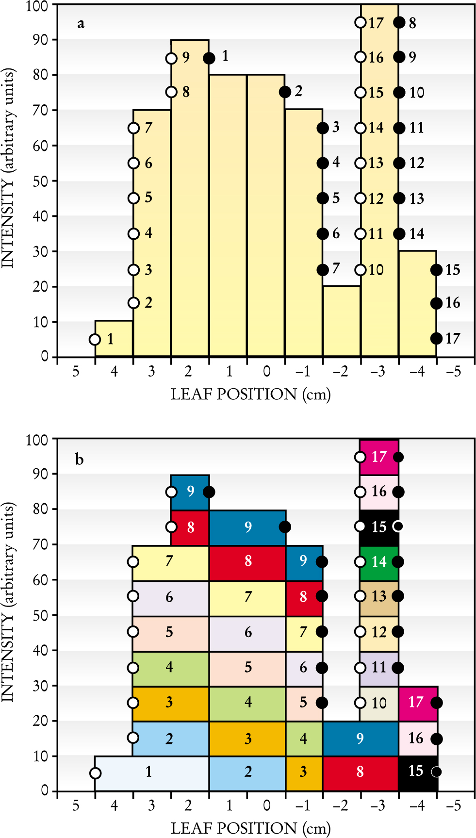
Let us designate the leaf inserted into the field from the left as the A-leaf and the leaf inserted into the field from the right as the B-leaf. The intensity pattern slice corresponding to the track of this leaf pair is produced by a sequence of gaps between the A-leaf and the B-leaf: Radiation passes through the gaps to accumulate the desired intensity profile. The sequence of positions of leaf ends that form these gaps can be determined by three simple steps. First, one determines the coordinates at which the intensity profile along the track passes through the center of each intensity level, indicated by circles in figure
The above procedure is termed the “step and shoot” method: Before radiation is initiated, the MLC controller steps the leaf ends to set the first gap and then signals to the linac controller to shoot a burst of radiation (lasting less than 1 second) through the gap. The linac then temporarily stops producing x rays as the MLC controller steps the leaves to the next gap. When the MLC controller determines that the leaves are in the specified positions (which takes a fraction of a second), another burst of radiation is produced. The sequence continues through 17 steps in the example depicted in figure 3.
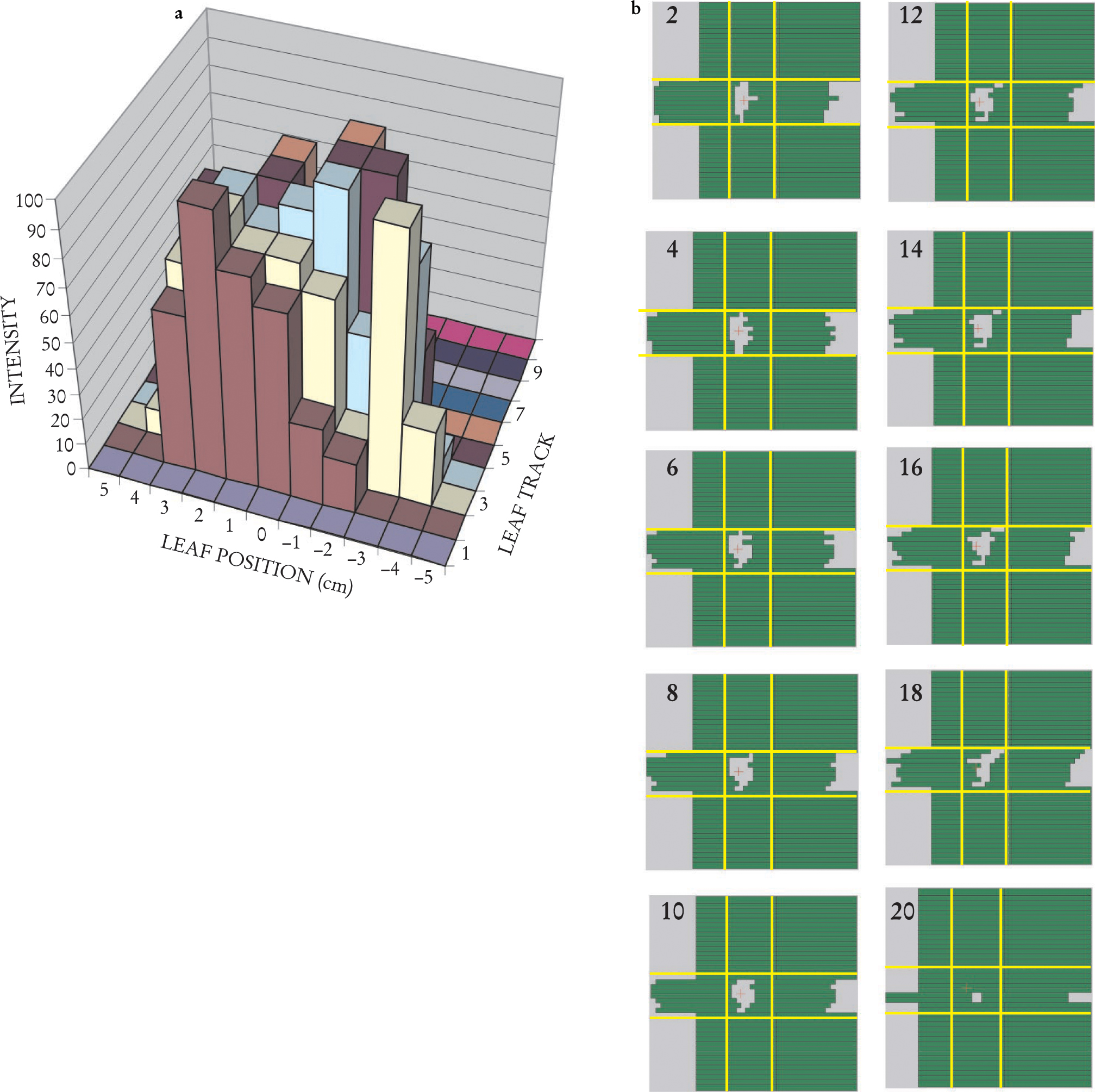
The procedure readily generalizes to all leaf tracks that cross the aperture; thus, one arrives at a sequence of gaps for each leaf pair. Taken together, the one-dimensional gaps between each pair of leaves form a two-dimensional window that sweeps across the x-ray beam, delivering dose to accumulate the desired cone-beam intensity pattern. For example, the multileaf track intensity pattern of figure 4(a) (in which the yellow track is the case considered in figure 3) can be generated through the sweeping windows of figure

Delivering a two-dimensional Intensity Pattern. (a) A 2D intensity map for the exposure from a single direction can be assembled by combining several individual-leaf track intensity patterns, such as the one in figure
A moment’s reflection on figure 3 will reveal that a large number of different gap sequences can all deliver the same intensity pattern. Different constraints imposed by particular MLC setups can influence which sequences are most efficient.
With the fixed cone-beam techniques, acceptable dose distributions can be achieved using five to nine beam directions. Dose distributions can be improved somewhat by optimizing the selection of the beam directions. Nearly 40 years ago, Shinji Takahashi from Nagoya, Japan, proposed using a rotating x-ray source for radiotherapy and continuously adjusting the beam shape to match the projection of the target volume.10 The original Takahashi unmodulated rotating cone beam has now been implemented11 and produces nearly optimal dose distributions. A natural evolution is to develop a continuously rotating cone beam form of IMRT. The problem is to determine the leaf sequence for that approach. One method suggested by Cedric Yu uses only a small number of intensity levels to optimize the dose delivery for a large number of gantry angles.12 The resulting intensity patterns are split into subapertures that vary as smoothly as possible from one gantry angle to the next for each intensity level. The treatment is then delivered using multiple rotations of the gantry, moving alternately clockwise and counterclockwise around the patient.
Clinical examples
Visualizing 3D dose distributions is difficult. Within a 2D slice, however, isodose lines can be drawn through points of equal dose to characterize the dose distributions within a single plane. For example, figure 5 shows the dose distribution in a clinical application of IMRT for treating the prostate gland. The prostate is in a difficult position to treat with radiation. It is situated beneath and behind the bladder, an organ whose inner lining becomes inflamed at a radiation dose that depends partly on the area being exposed. The rectum, whose inner walls are particularly sensitive to radiation, lies immediately behind the prostate. Prostate cancer tends to spread along lymph vessels that radiate sideways from the prostate toward the walls of the pelvis and proceed up out of the pelvis into the abdomen, where they pass beside and in front of the sacrum, behind the large and small bowel, and up to the lower lumbar vertebrae. Irradiating this complex, inverted-Y volume while sparing the bowel, bladder, and rectum would not be feasible without IMRT. With IMRT, as figure 5 shows, the sensitive tissues can be largely avoided.13

IMRT dose delivery in the pelvis. Lines of constant x-ray dose of a prostate cancer treatment are displayed here over a section of a CT scan in the pelvis. The image plane, indicated by the yellow line in the inset, is viewed from below. The plane is above the prostate target but includes lymph nodes (purple), which are a route of spread of the cancer. The IMRT treatment concentrates the delivered dose onto the lymph nodes. The bladder (yellow) and the rectum (green), both organs at risk, receive a lower dose. The small bowel (blue) is also spared.
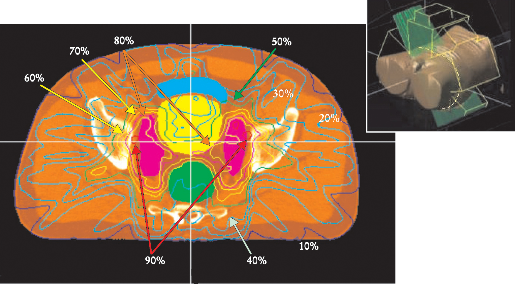
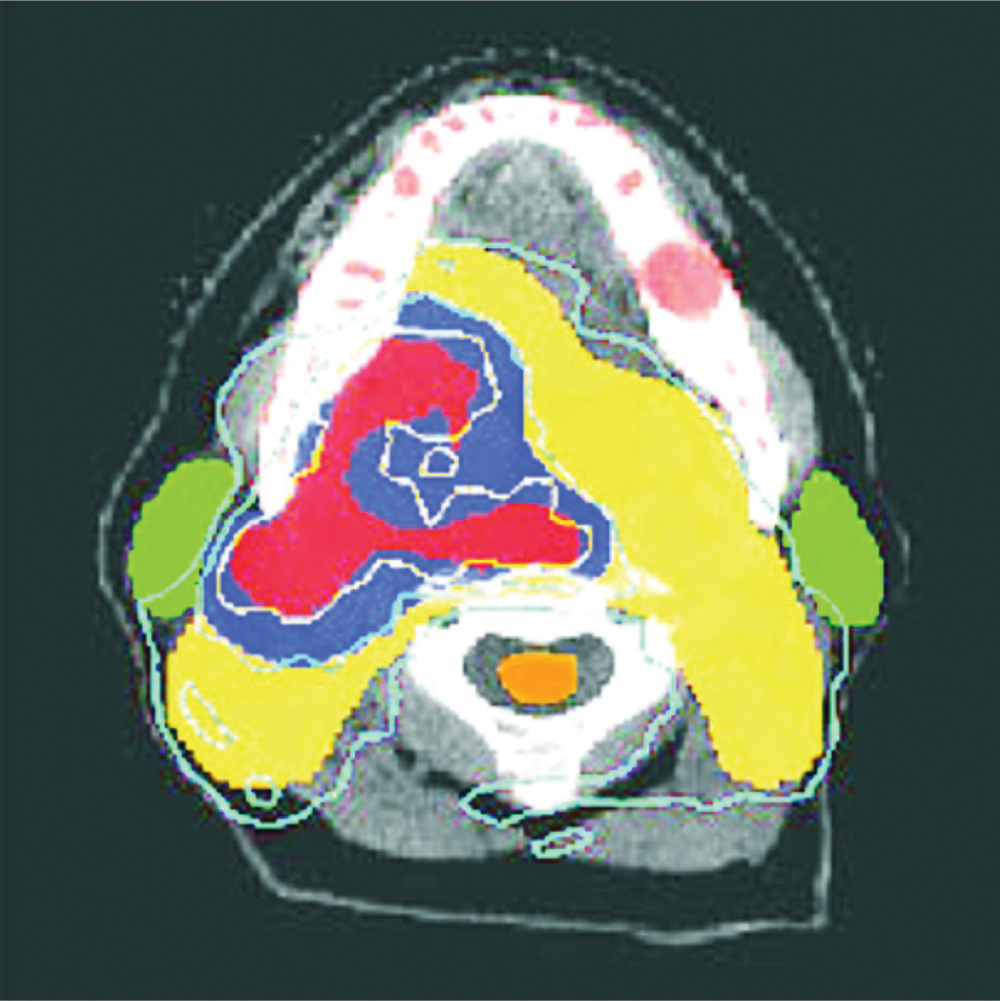
Figure 6 provides another example of IMRT treatment. 14 In this case, the tumor has originated in the base of the tongue. Such tumors spread along the cervical lymph-node chains that run down along each side of the neck. The parotid glands on either side of the jaw are susceptible to radiation damage, which results in reduced production of saliva. Besides being extremely uncomfortable, xerostoma, or dry mouth, can make it difficult for the patient to maintain the diet needed during therapy and can result in long-term damage to gums and teeth. Exceeding the tolerance of the spinal cord can lead to nerve damage or even permanent transection of the spinal cord in the neck, causing paralysis or death. An IMRT treatment that spares these structures allows the delivery of sufficiently high doses to the target volume to improve the chances of controlling the tumor.

IMRT treatment in the head for a tumor at the base of the tongue and right tonsil. This CT reconstruction plane shows the base of the head from below; the white arc is the lower jaw. The colored regions are cross sections through the planned treatment target volumes, identified from positron emission tomography (PET) and contrast-enhanced CT. In the red region, the PET scan showed high oxygen deficiencies, which indicates tumor cells. The 80-gray isodose line (1 Gy = 1 J/kg) surrounding this region shows that the region received a dose of 80 Gy or higher. The contrast-enhanced CT scan indicated possible growth of tumor cells into the blue region. The IMRT delivered 70 Gy to this region. The yellow target was formed to account for known patterns of spread into lymph nodes; that area received a dose of 50 Gy. The parotid glands (green) were spared the higher doses and will continue to function to produce saliva. The spinal cord (orange) was shielded to receive lower that 35 Gy, safely below the dose that can cause neural damage.
(Courtesy of Clifford Chao, University of Texas Cancer Center.)
Opportunities for the future
Although impressive progress has been made developing IMRT and integrating it into clinical practice, a host of areas beg for further investigation. Improvements in the technology continue to provide new capabilities of radiation delivery that can be exploited.
A fundamental unsolved problem in radiotherapy is the precise location of the tumor itself. The grayscale images reconstructed by modern volumetric imaging technology do not clearly distinguish between tumors and normal structures. However, the fields of tumor biology and medical imaging are advancing rapidly. Tumor biology is benefiting from improvements in magnetic resonance imaging, CT, and positron emission tomography for identifying the location of malignant tissue. Target imaging technology will perhaps be the most active area of investigation for the foreseeable future.
Delivering a complex radiation treatment is akin to conducting a nuclear physics experiment on a target that is an organ within a breathing human. The treatments must be repeated precisely each day for about six weeks with very little time allotted for positioning the patient at the beginning of the treatment session. A number of technologies are being investigated to help reposition the patient daily and compensate for patient respiration during treatment.
Flat-panel amorphous silicon (AmSi) detector arrays have been developed to detect high-energy x rays with a pixel size of less than 1 mm on a side (see the article by John Rowlands and Safa Kasap in Physics Today, November 1997, page 24 ). The detectors can acquire 40 × 30-cm images at acquisition rates of up to 15 frames per second with excellent signal-to-noise characteristics. Images acquired by the AmSi detectors using the high-energy x rays transmitted through the patient can be used to verify the daily positioning of the patient. Real-time AmSi imaging during the treatment is also being explored. The sweeping window and other IMRT techniques are not compatible with using the treatment beam to form the image. Instead, additional fixed x-ray tubes placed around the patient have been used with fixed AmSi detectors and high-density reference markers implanted in the patient to investigate this form of real-time tracking. Optical tracking that uses active or passive markers placed at reproducible locations on the patient’s skin surface is another option.
Although a patient can stay relatively still during each 15-minute treatment session, breathing motion can produce sufficient displacement to disturb the planned treatment delivery. One possible solution is to gate the x-ray beam in synchrony with the patient respiration cycle. Alternatively, the x-ray beam can be redirected to track the moving target volume, either by making real-time adjustment to the MLC leaf positions or by adjusting the direction of the entire beam. Correcting for respiratory motion is complicated by the anatomical and medical variances that occur within human patients.
Imprecision in the prediction of the dose deposited throughout the patient can lead to insufficient cell death in the tumor volume or excessive tissue damage in normal structures. A significant effort is under way to precisely model dose deposition using simulations based on detailed histories of the photon and electron interactions in tissues whose density distributions are provided by 3D CT data sets of the patient in treatment position. That work is being aided by the availability of ever cheaper and faster computers.
More about the authors
Arthur Boyer (boyer@reyes.stanford.edu ) is director of the division of radiation physics in the department of radiation oncology at the Stanford University School of Medicine in Stanford, California.
Arthur L. Boyer, 1(boyer@reyes.stanford.edu) Stanford University School of Medicine in Stanford, California, US .


