Reversing Light With Negative Refraction
DOI: 10.1063/1.1784272
Victor Veselago, in a paper
1
published in 1968, pondered the consequences for electromagnetic waves interacting with a hypothetical material for which both the electric permittivity
Veselago always referred to the materials as “left handed,” because the wave vector is antiparallel to the usual right-handed cross product of the electric and magnetic fields. We prefer the negative-index description. The names mean the same thing, but our description appeals more to everyday intuition and is less likely to be confused with chirality, an entirely different phenomenon.
Why are there no materials with negative
Although somewhat less common than positive materials, negative materials are nevertheless easy to find. Materials with negative
That negative material parameters occur near a resonance has two important consequences. First, negative material parameters will exhibit frequency dispersion: They will vary as a function of frequency. Second, the usable bandwidth of negative materials will be relatively narrow compared with positive materials. These consequences can help answer our initial question as to why materials with
Metamaterials extend material response
Because of the seeming separation in frequency between electric and magnetic resonant phenomena, Veselago’s analysis of materials with
To form an artificial material, we start with a collection of repeated elements designed to have a strong response to applied electromagnetic fields. As long as the size and spacing of the elements are much smaller than the electromagnetic wavelengths of interest, incident radiation cannot distinguish the collection of elements from a homogeneous material. We can thus conceptually replace the inhomogeneous composite by a continuous material described by material parameters
A metamaterial mimicking the Drude–Lorentz model can be straightforwardly achieved with an array of wire elements into which cuts are periodically introduced. The effective permittivity for the cut-wire medium has the form
The path to achieving magnetic response from conductors is slightly different. From the basic definition of a magnetic dipole moment, m =
In 1999, one of us (Pendry) and colleagues proposed a variety of structures that, they predicted, would form magnetic metamaterials.
2
Those structures consisted of loops or tubes of conductor with a gap inserted. One can view such structures as miniature circuits: A time-varying magnetic field induces an electromotive force in the plane of the element, driving currents within the conductor. A gap in the plane of the structure introduces capacitance into the planar circuit and gives rise to a resonance at a frequency set by the geometry of the element. Such a splitring resonator (SRR), in its various forms, can be viewed as the metamaterial equivalent of a magnetic atom. The SRR medium could be described by the resonant form
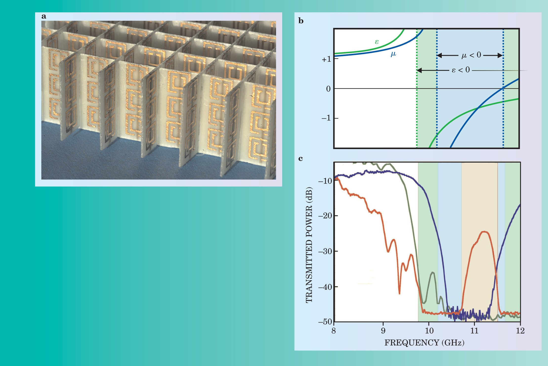
The wire medium and the SRR medium represent two basic building blocks—one electric, the other magnetic—for a large range of metamaterial response, including Veselago’s hypothesized material (see figure 1).

Figure 1. Metamaterials can be designed to create negative refraction. (a) In this example of a metamaterial used in microwave experiments, unit cells consist of a split-ring resonator and a wire spanning the cell, just visible on the reverse of the supporting sheets. (b) Schematic variation of
Negative refraction
Maxwell’s equations determine how electromagnetic waves propagate within a medium and can be solved to arrive at a wave equation of the form
In this equation,
It turns out that one needs to be more careful in taking the square root, because
This briefly stated argument shows why the material Veselago pondered years ago is so unique: The index of refraction is negative. A negative refractive index implies that the phase of a wave decreases rather than advances with passage through the medium. As Veselago pointed out, this fundamental reversal of wave propagation contains important implications for nearly all electromagnetic phenomena. Many of the exotic effects of negative index have been or are currently being pursued by researchers. But perhaps the most immediately accessible phenomenon from an experimental or computational point of view is the reversal of wave refraction, illustrated in figure 2.

Figure 2. A negative-index material will refract light through a negative angle. (a) In this simulation
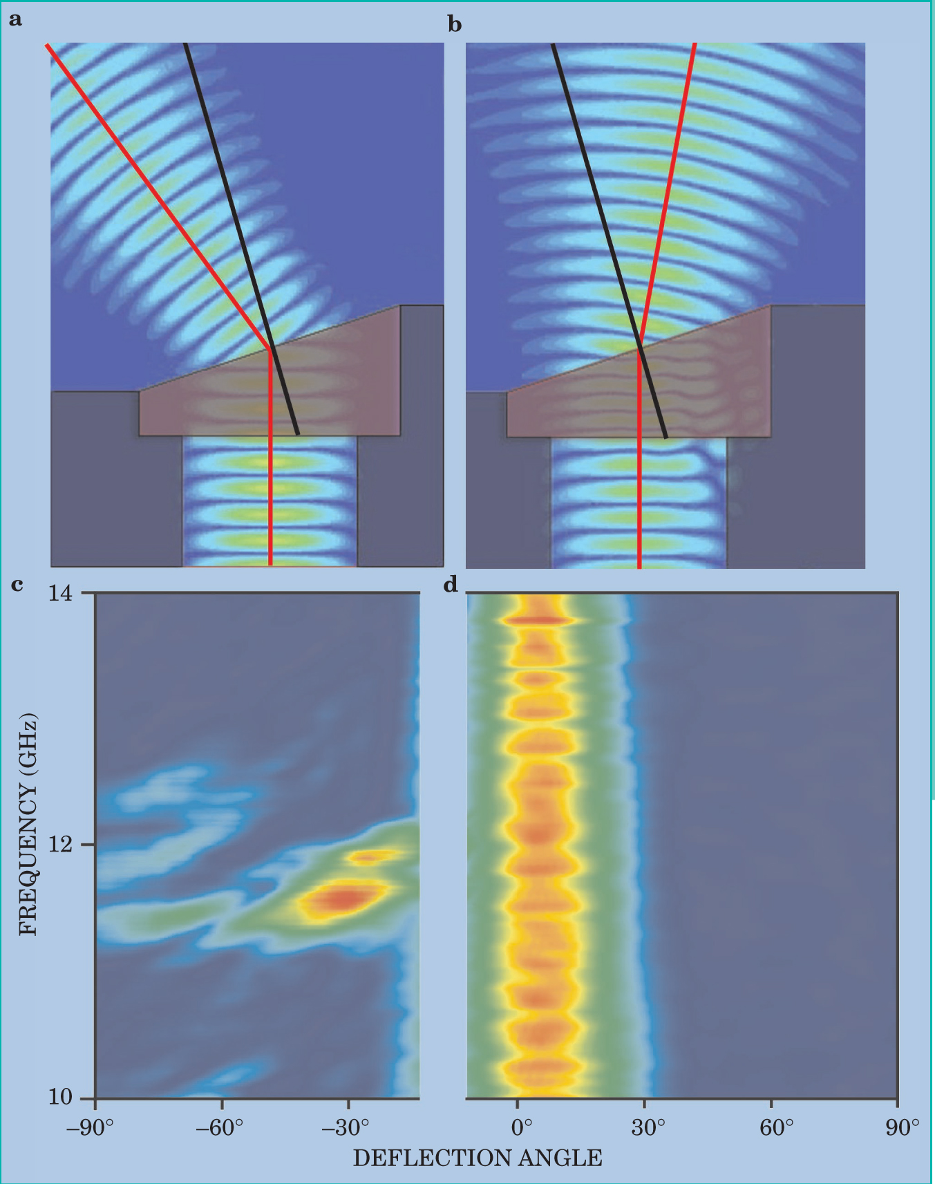
Snell’s law, which describes quantitatively the bending of a wave as it enters a medium, is perhaps one of the oldest and most well known of electromagnetic phenomena. In the form of a wedge refraction experiment, as depicted in figure 2, Snell’s law is also the basis for a direct measurement of a material’s refractive index. In this type of experiment, a wave is incident normal to a wedge-shaped sample. The wave is transmitted through the transparent sample and strikes the second interface at an angle. Because of the difference in refractive index between the material and free space, the beam exits the wedge deflected by some angle from the direction of incidence.
One might imagine that an experimental determination of Snell’s law would be a simple matter. The peculiarities of metamaterials, however, add a layer of complexity that renders the experimental confirmation somewhat more difficult. Present samples, based on SRRs and wires, are frequency dispersive with fairly narrow bandwidths and exhibit considerable loss. The first experiment showing negative refraction was performed in 2001 by one of us (Smith) and colleagues at the University of California, San Diego. 3 In an experiment similar to that depicted in figure 2, they measured the power refracted from a two-dimensional wedge-shaped metamaterial sample as a function of angle, confirming the expected properties.
While the UCSD data were compelling, the concept of negative index proved counterintuitive enough that many other researchers needed further convincing. In 2003, Andrew Houck and colleagues at MIT repeated the negative-refraction experiment on the same sort of negative-index metamaterial and confirmed the original findings. 4 Looking at wedges with different angles, the MIT group showed that the observed angle of refraction was consistent with Snell’s law for the metamaterial. In the same year, Claudio Parazzoli and coworkers at Boeing Phantom Works also confirmed the negative-refraction results in a separately designed sample. 5 In their measurements, the detector’s distance from the sample was significantly larger than for previous demonstrations.
Although it has proven to be a valuable concept, a rigorously defined negative index of refraction may not necessarily be a prerequisite for negative-refraction phenomena. An alternate approach to attaining negative refraction uses the properties of photonic crystals, 6,7 materials that lie on the transition between a metamaterial and an ordinary structured dielectric. Photonic crystals derive their properties from Bragg reflection in a periodic structure engineered in the body of a dielectric, typically by drilling or etching holes. The periodicity in photonic crystals is on the order of the wavelength, so that the distinction between refraction and diffraction is blurred. Nevertheless, with photonic crystals many novel dispersion relationships can be realized, including ranges in which the frequency disperses negatively with wave vector as required for a negative refraction. Using photonic crystals, 8,9 researchers have observed focusing, as predicted for negative-index materials.
The concept of negative refraction has also been generalized to transmission-line structures, which are common in electrical engineering applications. By pursuing the analogy between lumped circuit elements and material parameters, George Eleftheriades and coworkers at the University of Toronto have demonstrated negative-refraction phenomena in microwave circuits. 10 The transmission-line model has proven exceptionally valuable for the development of microwave devices: Tatsuo Itoh and Christophe Caloz at UCLA have applied the model to develop novel microwave components, including antennas, couplers, and resonators. 11
Those experiments and applications have shown that the material Veselago hypothesized more than 35 years ago can now be realized using artificially constructed metamaterials; the discussion of negative refractive index is thus more than a theoretical curiosity. The question of whether such a material can exist has been answered, and the development of negative-index structures has turned into a topic of materials—or metamaterials—physics. As metamaterials are being designed and improved, we are now free to consider the ramifications associated with a negative index of refraction. That material property, perhaps because it is so simply stated, has enabled the rapid design of new electromagnetic structures—some with very unusual and exotic properties.
A better focus
Refraction is the phenomenon responsible for lenses and similar devices that focus or shape radiation. Although usually thought of in the context of visible light, lenses are utilized throughout the electromagnetic spectrum; they thus represent a good starting point to implement negative index materials.
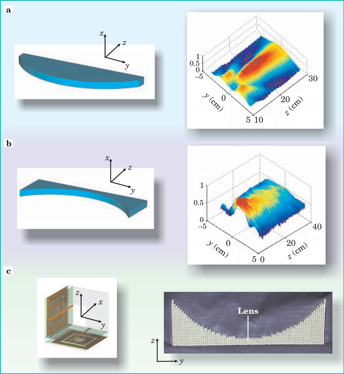
In his early paper, Veselago noted that a negative-index focusing lens would need to be concave rather than convex—a seemingly trivial matter, but there is more to the story. For thin lenses, geometrical optics—valid for either positive or negative index—gives the result that the focal length

Figure 3. Lightweight, compact lenses can be designed from metamaterials to be relatively free of aberration. (a) A positive-index lens with an index of refraction
Making a conventional lens with the best possible resolution requires a wide aperture. Each ray emanating from an object, as shown in figure 4(a), has wave vector components along the axis of the lens,

Figure 4. Resolution limitations. (a) For good resolution, conventional lenses need a wide aperture to refract rays at large angles θ, but even so, they are limited in resolution by the wavelength used. (b) The missing Fourier components of the image are contained in the near field, which decays exponentially (blue curve) and makes negligible contribution to the image. (c) A lens made from a planar slab of negative-index material not only brings rays to a focus but has the capacity (d) to amplify the near field so that it contributes to the image. Such a negative lens thus removes the wavelength limitation. However, the resonant nature of the amplification places severe demands on materials: They must be very low loss.
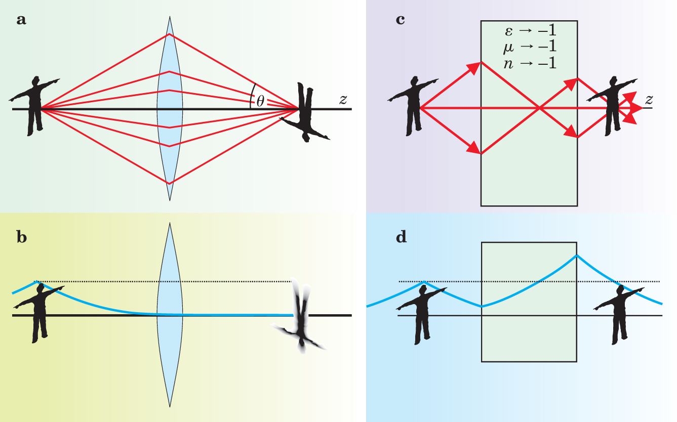
In contrast to the image, the object has no limit to its electromagnetic details, but unfortunately not all of that information makes it across the lens to the image. The problem lies with the wave vector’s
If by some magic we could amplify the near fields, we could in principle recoup their contribution, but the amplification would have to be of just the right amount and possibly very strong for the most localized components. That is a tall order, but by a remarkable chance, a planar slab of negative material achieves this feat. 12
Figure
In the case of evanescent waves, amplification does not imply a sustained input of power. Evanescent waves carry no power and hence, in the absence of loss, a large-amplitude evanescent wave can be sustained indefinitely in a purely passive medium.
For a conventional lens, resolution is limited by the aperture. This new lens based on negative materials will also, in practice, have limitations, chiefly due to losses. Any real material will always have small, positive imaginary components to
Nick Fang and colleagues
13
have explored near-field amplification by exploiting the fact that for very small systems—much smaller than the free-space wavelength—the electric and magnetic fields are independent of one another and can be controlled separately. Therefore if one is only concerned with the electric fields,
Silver has a negative real part to
With a microwave transmission-line lens, Eleftheriades’s group in Toronto 10 has recently realized conditions for subwavelength focusing and produced images significantly enhanced by evanescent-wave amplification. The image resolution of about λ/5 was consistent with losses in the system; reducing the loss would improve resolution even further.
Negative refraction as negative space
A slab of negative material with

Figure 5. Generalizing the perfect lens. (a) A slab with refractive index
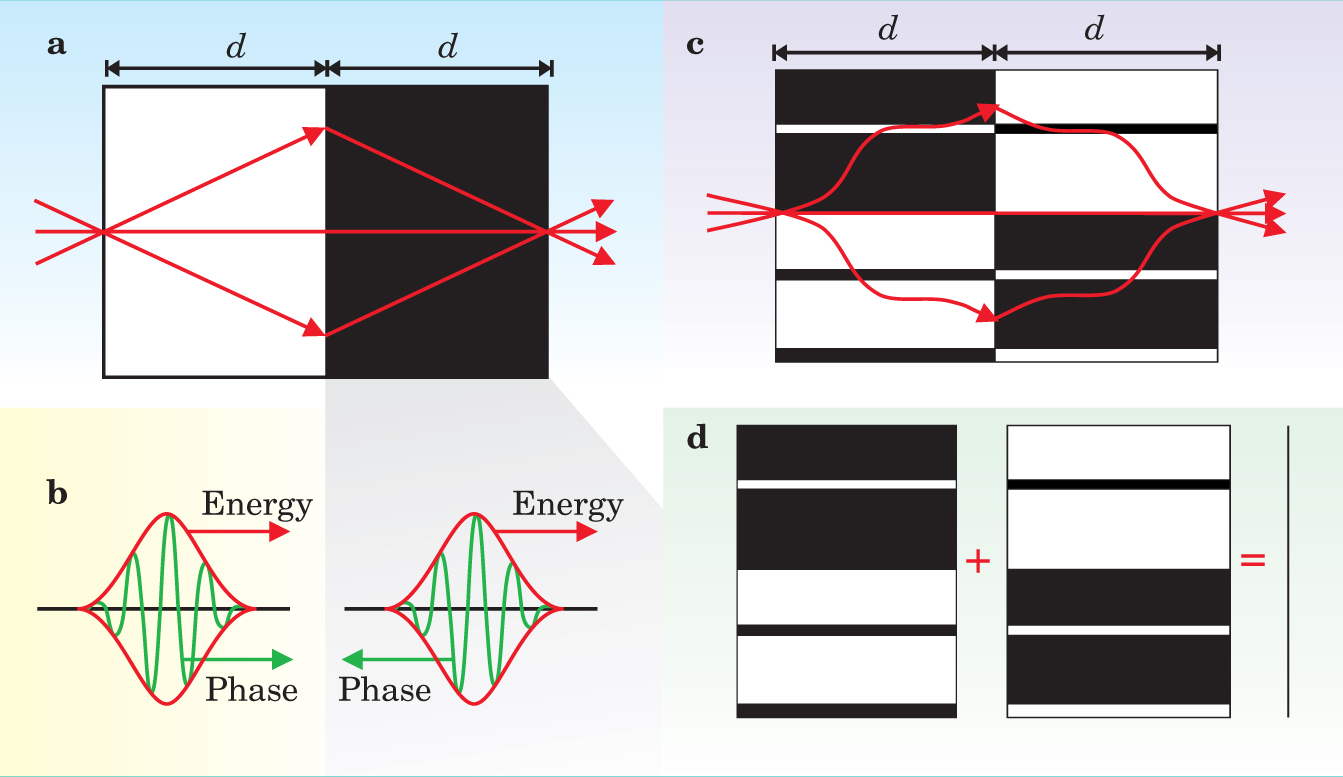
In fact, the result is more general.
14
Two slabs of material optically annihilate if one is the negative mirror image of the other—that is, if they meet in the plane
Figures
This result may seem straightforward, but some configurations have surprises. The two halves of figure 6(a) are inverse mirror images as required by the cancellation theorem, and therefore we expect that incident waves are transmitted without attenuation and without reflection. Yet a ray-tracing exercise holds a surprise. Ray 2 in the figure hits the negative cylinder and is twice refracted to be ejected from the system rather than transmitted. The rays don’t support our theorem!

Figure 6. An optical paradox. (a) Ray tracing predicts that some rays, such as ray 2, will be rejected from this system, even though the mirror theorem illustrated in figure
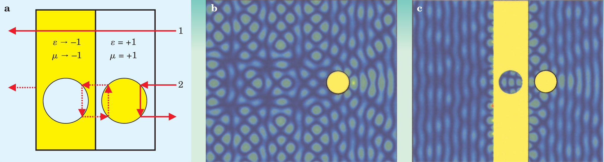
Further investigation shows that the cylinder is capable of trapping rays in closed orbits, shown by dotted lines in the center of the figure. Such closed paths are the signature of a resonance and a clue as to how the paradox is resolved. A full solution of Maxwell’s equations shows that when the incident light is first switched on, the ray predictions are initially obeyed. With time, some of the incident energy will feed into the resonant state in the middle of the system, which in turn will leak energy into a transmitted wave and into a contribution to the reflected wave that cancels with the original reflection. As always in negative media, resonant states play a central role.
Figures
An interesting question arises if there is absorption—represented by positive imaginary parts of either or both of
Building on the foundations
Negative refraction is a subject with constant capacity for surprise: Innocent assumptions lead to unexpected and sometimes profound consequences. This new field has generated great enthusiasm but also controversy, yet even the controversies have had the positive effect that key concepts have been critically scrutinized in the past 18 months. In the past year, experimental data have been produced that validate the concepts. As a result, we have a firm foundation on which to build. 15 Many groups are already moving forward with applications. The microwave area has naturally been most productive, because the metamaterials required are easier to fabricate. In addition to microwave lenses, novel waveguides and other devices are under consideration.
One of the most exciting possibilities is imaging beyond the wavelength limit. Practical applications will require low-loss materials, which are a great challenge to the designers of new metamaterials. Proposals to employ thin silver films as lenses are being explored in several laboratories. And the challenges are not purely experimental: We are not yet done with theory, because the assumption of negative refraction has many ramifications that are still being explored and are sure to cast more light on this strange but fascinating subject. Not surprisingly, many researchers are joining the field: 2003 saw more than 200 papers published on negative refraction. We expect even more in 2004!
References
1. V. V. Veselago, Sov. Phys. Usp. 10, 509 (1968).https://doi.org/10.1070/PU1968v010n04ABEH003699
2. J. J. Pendry, A. A. Holden, D. D. Robbins, W. W. Stewart, IEEE Trans. Microwave Theory Tech. 47, 2075 (1999).https://doi.org/10.1109/22.798002
3. R. R. Shelby, D. D. Smith, S. Schultz, Science 292, 77 (2001).https://doi.org/10.1126/science.1058847
4. A. A. Houck, J. J. Brock, I. I. Chuang, Phys. Rev. Lett. 90, 137401 (2003).https://doi.org/10.1103/PhysRevLett.90.137401
5. C. C. Parazzoli, R. R. Greegor, K. Li, B. E. C. Koltenbah, M. Tanielian, Phys. Rev Lett. 90, 107401 (2003).https://doi.org/10.1103/PhysRevLett.90.107401
6. M. Notomi, Phys. Rev. B 62, 10696 (2000).https://doi.org/10.1103/PhysRevB.62.10696
7. C. Luo, S. S. Johnson, J. J. Joannopoulos, J. J. Pendry, Opt. Express 11, 746 (2003).https://doi.org/10.1364/OE.11.000746
8. P. P. Parimi, W. W. Lu, P. Vodo, S. Sridhar, Nature 426, 404 (2003).https://doi.org/10.1038/426404a
9. E. Cubukcu, K. Aydin, E. Ozbay, S. Foteinopolou, C. C. Soukoulis, Phys. Rev. Lett. 91, 207401 (2003).https://doi.org/10.1103/PhysRevLett.91.207401
10. A. Grbic, G. G. Eleftheriades, Phys. Rev. Lett. 92, 117403 (2004).https://doi.org/10.1103/PhysRevLett.92.117403
11. L. Liu, C. Caloz, T. Itoh, Electron. Lett. 38, 1414 (2002).https://doi.org/10.1049/el:20020977
12. J. J. Pendry, Phys. Rev. Lett. 85, 3966 (2000).https://doi.org/10.1103/PhysRevLett.85.3966
13. N. Fang, Z. Liu, T. T. Yen, X. Zhang, Opt. Express 11, 682 (2003).https://doi.org/10.1364/OE.11.000682
14. J. J. Pendry, S. S. Ramakrishna, J. Phys.: Condens. Matter 14, 6345 (2003).https://doi.org/10.1088/0953-8984/15/37/004
15. Further reading can be found in a special edition ofOpt. Express, “Focus Issue: Negative Refraction and Metamaterials,” 11, 639–755 (April 2003), and in
M. M. McCall, A. Lakhtakia, W. W. Weiglhofer, Eur. J. Phys. 23, 353 (2002).https://doi.org/10.1088/0143-0807/23/3/31416. R. R. Shelby, D. D. Smith, S. S. Nemat-Nasser, S. Schultz, Appl. Phys. Lett. 78, 4 (2001).https://doi.org/10.1063/1.1343489
17. P. Kolinko, D. D. Smith, Opt. Express 11, 640 (2003).https://doi.org/10.1364/OE.11.000640
18. C. C. Parazzoli, R. R. Greegor, J. J. Nielson, M. M. Thompson, K. Li, A. A. Vetter, M. M. Tanielian, Appl. Phys. Lett. 34, 3232 (2004).https://doi.org/10.1063/1.1728304
More about the authors
John Pendry
John B. Pendry, 1 Imperial College, London, UK .
David R. Smith, 2 University of California, San Diego, US .


