Microscopy without lenses
DOI: 10.1063/PT.3.3693


Since its invention, the classical optical microscope and its successive variants have generally relied on one key element: the objective lens. The objective lens can be a single or compound lens that typically has a short focal length and large numerical aperture, NA = n sinθ, where n is the refractive index of the medium between the objective lens and the sample, and θ is the maximum acceptance angle of the lens. The short focal length facilitates the incorporation of the objective into an optical system with a large magnification so that microscopic objects can be observed by human eye or with a digital camera. The large numerical aperture of the objective enables a well-designed imaging system to resolve microscopic features down to the classical limit of approximately λ/2 NA for incoherent light, where λ is the wavelength of the light.
Microscopes have become much more advanced in recent years. Nonetheless, the use of the microscope objective continues to create some important limitations. One particular limitation is that the imaging field of view is tied to the spatial resolution through a quantity known as the space–bandwidth product, which is proportional to the area of the field of view divided by the area of the smallest resolvable feature. Mathematically similar to the Heisenberg uncertainty principle, the space–bandwidth product is a measure of the information capacity of an imaging system. Microscopy approaches that possess high space–bandwidth products are particularly well suited to provide solutions for needle-in- a-haystack problems. For example, screening tissue slices or cell smears for indications of cancer requires the imaging of a large number of cells, and large sample volumes, with sufficiently high resolution to observe subcellular features in individual cells. For analog optical microscopes, which do not use any digital computation or algorithms to form images, the space-bandwidth product is governed by the diffraction of light and by the aberrations and the field of view of the imaging system.
To practically improve the space–bandwidth product in a conventional lens-based microscope, one would seek an objective lens that simultaneously has a low magnification and high NA. While it is possible to find objectives with low magnification (less than 10×) and moderate NA (greater than 0.5), they tend to cost thousands of dollars due to the fabrication and design tolerances necessary to precisely correct optical aberrations across a large field of view at high-resolution. Objective lenses with lower magnifications (in the range of 1× to 2×) and higher NA (near 1.0) are nonexistent, at least commercially. Altogether, microscopy systems that incorporate moderate- to high-NA objectives are relatively large (often larger than 0.1–0.2 m3) and expensive (for example, more than $30 000), which partially limit their widespread use, especially in resource limited settings.
In the past decade or so, another approach—lens-free microscopy—has gained traction.
1–3
As sketched in figure
Figure 1.

Lens-free on-chip microscopy (a) requires only a light source, a transparent sample, and an image sensor. (b, c) Lens-free microscopes can be readily implemented as compact, field-portable, and cost-effective devices. (Adapted from ref.
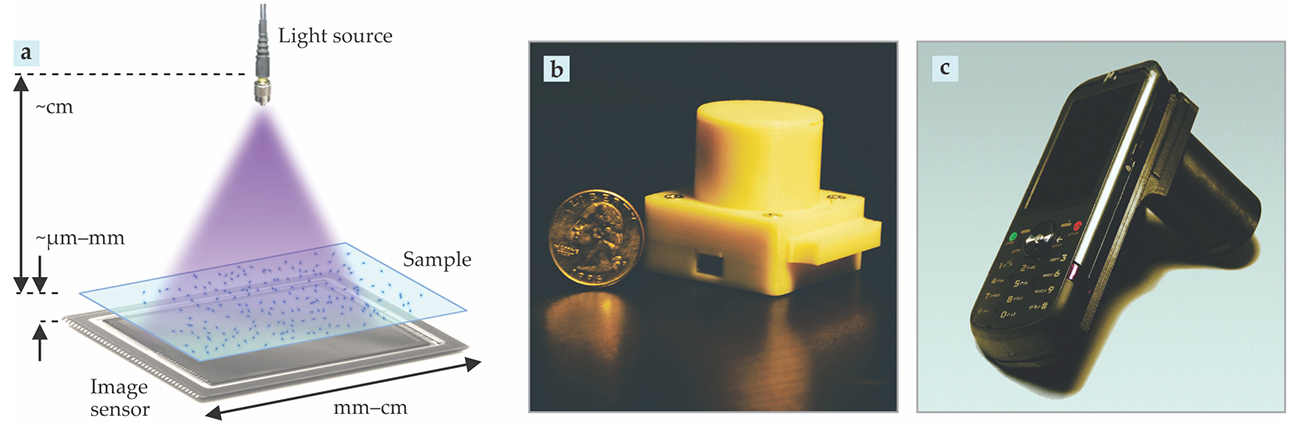
Two main reasons behind the success of lens-free microscopy are the mass production of inexpensive high-resolution CMOS image sensors used in consumer electronics and the increase in the computational power of laptops, tablets, smartphones, and other mobile devices. 4 Benefiting from economies of scale, lens-free on-chip imaging enables lightweight, compact, and inexpensive microscopy platforms for use in, for example, field work related to environmental monitoring and sensing, at medical clinics and other point-of-care settings, and in global health applications for rapid and accurate analysis of samples in remote regions. Below we expound on several different “flavors” of lens-free microscopy, which address different aspects of some of those applications.
Shadow and fluorescence imaging
Shadow imaging is one of the simplest configurations of lens-free on-chip imaging. Because the imaging system has no lens, the frames captured by the image sensor are governed by the optical diffraction that occurs between the sample and sensor planes. As a result, lens-free images form as relatively blurry, out-of-focus shadows of the samples. In most implementations of lens-free on-chip imaging, the light source aperture is relatively small—less than 0.1 mm—and the source–sample distance is much greater than the sample–sensor distance. Therefore, the spatial blurring due to the size of the light source aperture is negligible compared to diffraction-induced blur.
Although the shadow images can be blurry, they may nonetheless be useful for applications where high resolution is not required, such as the counting of objects with sizes in the range of tens of microns. 5 , 6 One notable example is the tracking of the growth and migration of cells with a compact lens-free imaging system placed inside an incubator with the cell culture. In this application, it may be unnecessary to resolve subcellular details, and it is possible to use pattern-matching algorithms to discriminate between different types of cells based on their two-dimensional shadow patterns.
An approach to improve the resolution in shadow imaging is to flow the sample in a microfluidic channel across an array of apertures in what has been called an optofluidic microscope. 7 As an object moves across the aperture array, the microscope sequentially acquires multiple image frames. Each frame captures light from only a small fraction of the object, but at a resolution determined by the aperture size and object–aperture vertical distance, both of which can be quite small compared with the sample–sensor distance. Provided that the object traverses the aperture array without rolling or tumbling, the microscopist can digitally create, from the many individual frames, an image of the object with improved resolution. Lens-free optofluidic microscopes 8 that do not need an array of apertures have also been demonstrated based on holographic imaging principles—more on holographic imaging later.
In terms of resolution, lens-free fluorescence imaging is similar to shadow imaging. As with conventional fluorescence microscopy, short wavelength light excites fluorophores that then emit light at a longer wavelength. A simple on-chip implementation involves inserting an absorption-based optical filter between the sample and the image sensor in order to pass the fluorescence emission while blocking the excitation source.
For improved rejection of the excitation source in a lens-free on-chip fluorescence microscope, light may be delivered through a total internal reflection scheme using, for example, a prism or a hemisphere. Fluorescent objects can be suspended within a microfluidic channel that is bounded on the top and bottom by glass. Between the glass and the image sensor chip, an air gap causes the near-grazing-incidence excitation light to be totally reflected at the glass–air interface, whereas most of the isotropically emitted fluorescence light is transmitted through to the image sensor. Due to optical diffraction between the sample and the sensor planes and the isotropic emission from the fluorophores, the captured frames are relatively blurry.
From a hardware standpoint, ultra-thin filters or filters incorporated directly on the active area of the image sensor chip can be used to minimize the sample–sensor distance and thereby boost spatial resolution. Deconvolution and compressive sampling based techniques have also been used to algorithmically improve resolution. Deconvolution attempts to mathematically “divide out” the blurring effects of diffraction and aberrations in order to sharpen the image. Compressive sampling makes an additional assumption that the object is approximately sparse (most pixel values are zero), either naturally, as with a fluorescently tagged object, or in some mathematical basis. In such cases, the fine features of an object can be reconstructed from a smaller number of measurements—for example, using a smaller number of pixels than would be required under the Nyquist–Shannon sampling theorem.
Even when the image is not naturally sparse, with some knowledge of the sample being imaged, one can generally find a sparsifying basis. For example, a Fourier transform or a wavelet transform might render the data sparse. The amount of resolution improvement is still partially limited by the signal-to-noise ratio of each measurement. Even with the hardware and software techniques discussed here, the best fluorescence resolution for an on-chip microscope is practically limited to a few microns.
Holographic on-chip imaging
Holographic on-chip imaging provides a way to significantly enhance resolution in order to approach the diffraction limit of light. If the light source used in the lens-free setup is at least partially coherent and the sample to be imaged is transmissive, then the interference between the reference light that passes through the sample and the signal light that scatters off of objects in the sample volume will produce an in-line hologram. The microscopist can reconstruct an in-focus image of the object from this digitally recorded hologram, assuming its phase can be recovered—more on phase recovery later. A common, computationally efficient way to reconstruct a holographic image is the angular spectrum method: Fourier transform the hologram, multiply the result with a term that represents how the light wave accumulates phase as it propagates, and then inverse Fourier transform the product.
In conventional microscopy, resolution is limited by the numerical aperture of the objective lens. The resolution of the lens-free holographic reconstruction is limited by a number of key parameters: the temporal and spatial coherence of the light source, the pixel size of the sensor, and ultimately by the refractive index of the medium that fills the free space between the sample and sensor planes.
It is relatively straightforward to engineer the spatial and temporal coherence of a light source, even one that is typically considered incoherent, such as an LED. For example, spatial coherence can be increased by using a smaller aperture or lengthening the source–sample distance. Temporal coherence can be increased with a bandpass filter to narrow the illumination bandwidth. Assuming the coherence of the illumination is sufficient, the first significant limit that is typically encountered is the pixel size of the sensor, which, for commercially available sensors, is currently 1 µm or larger. In imaging systems with pixel-limited resolution, techniques collectively known as pixel superresolution have been developed to overcome this pixelation limit. 9 Note that pixel superresolution does not overcome the diffraction limit and is fundamentally different from the recent generation of fluorescent superresolution techniques.
In pixel superresolution, multiple low-resolution frames are acquired where the object or its shadow is translated across the sensor plane by a noninteger number of pixels between any two frames. After aligning, or registering, each frame with respect to some global coordinate system, the set of subpixel-shifted low-resolution image data can be used to synthesize a high-resolution image. The resolution of the synthesized image is limited by the signal-to-noise ratio of the raw frames and, ultimately, by the refractive index of the medium between the sample and sensor planes, which defines the maximum achievable NA under vertical illumination.
Pixel superresolution has been used to reconstruct images of microscopic specimens
5
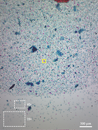
with an NA that is equivalent to about 0.9 over a field of view of 20 mm2. A comparable 0.9 NA microscope objective would typically have a field of view of only 0.01 mm2, and therefore a space–bandwidth product that is orders of magnitude smaller. To better illustrate this, figure
Figure 2.

Field of view. A typical lens-free on-chip image of a Papanicolaou (Pap) smear is shown. The two dashed boxes at the bottom left of the image indicate the much smaller fields of view that conventional 40× and 20× microscope objectives would typically provide. The area enclosed in the yellow box is shown in detail in figure
An even higher NA of 1.4 has been demonstrated in lens-free on-chip imaging using the pixel superresolution framework at multiple illumination angles. 1 , 10 The general approach of using multiple illumination angles to boost resolution in coherent imaging systems is referred to as synthetic aperture. Originally developed for radar applications, this approach can extend the effective NA of the computed image of a 2D specimen beyond the refractive index of the medium that fills the space between the sample and sensor planes.
Imaging in 3D
Another important advantage of lens-free holographic on-chip imaging over conventional microscopy is that the focusing is performed computationally during image reconstruction, rather than by mechanical translation or focusing at the time of image capture. Consequently, the captured data can be reconstructed, or re-focused, at an arbitrary plane of interest. This approach can also be used to track moving objects in three dimensions.
Typically, the depth resolution of the reconstructed image is several times worse than the lateral resolution. However, this limitation for 3D tracking of objects can be overcome with a dual illumination scheme in which one LED source is directed at normal incidence while a second LED is directed at an oblique angle. The reconstruction of the hologram generated by the two light sources that are simultaneously on can be used to precisely triangulate the object position in three dimensions. Even though the CMOS imager does not have color filters—a monochrome sensor—separation of the vertical and oblique perspectives of the sample from each other is nonetheless possible by selecting LEDs with center wavelengths spectrally far from each other—say, one blue and one red. As shown in figure
Figure 3.

Three-dimensional tracking of sperm cells. (a) More than 1500 human sperm cells were tracked within a volume of approximately 8 µL using a lens-free microscope. (b) A small percentage of sperm follow regular helical trajectories. The inset shows the projection of the trajectory onto a plane normal to the overall direction of the sperm motion, shown by the arrow. (Adapted from ref.
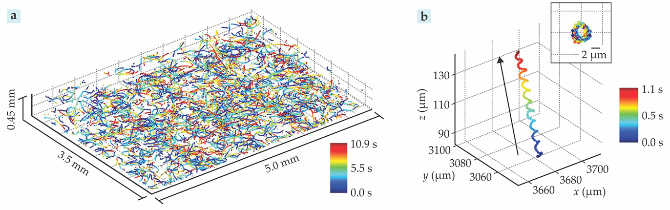
One of the interesting discoveries that resulted from the unique statistics provided by this large observation volume of the lens-free microscope was that a small fraction of sperms travel in regular helical patterns in vitro. Of those, 90% travel in a right-handed helix, whereas 10% travel in a left-handed helix. The reasons for that bias in chirality and under what conditions sperm cells prefer helical locomotion are, as of yet, unknown.
In addition to 3D tracking of microswimmers, more complex three dimensional objects can also be reconstructed using limited angle lens-free tomography on a chip. There, the object is viewed from several different angles in order to generate a 3D reconstruction. 5 , 8
Phase recovery
A drawback of in-line holography is that reconstructed images include an artifact known as the twin image. It arises from the inability to directly measure the phase of the light at the image sensor plane. In the reconstruction of the sample, this lost phase information manifests itself as the superposition of the accurately reconstructed object along with a pattern that would theoretically be generated from the same object, positioned on the opposite side of the sensor and illuminated in the opposite direction (forming the twin image).
By capturing multiple lens-free holograms with different sample-to-sensor distances, it is possible to resolve the phase ambiguity and eliminate the twin image artifact. Such techniques are collectively known as phase recovery. 12 Phase recovery with multiple sample-to-sensor distances generally relies on the principle that the amplitude of the light captured at each different plane must be consistent with the propagation of the light between the planes.
One iterative reconstruction strategy that utilizes multiheight measurement diversity to converge on the missing phase information proceeds as follows. A random guess is made for the phase at one of the measurement planes. The field formed by the measured amplitude and the guessed phase is then computationally propagated to the next plane of measurement using, for example, the angular spectrum method. At the second plane, the computed amplitude is replaced by the experimentally measured amplitude, but the computed phase is left intact. The field formed by the experimental amplitude and the computed phase is computationally propagated to the next plane of measurement, where, as before, the amplitude is updated and the phase is left intact. Those steps are repeated until convergence is achieved, that is, until all the phase and amplitude reconstructions from different measurement heights converge to the same object image, within a pre-defined error margin. The iterative method robustly eliminates the twin image problem, and also enables the imaging of dense and connected objects
13
such as tissue slices or Papanicolaou (Pap) smears (see figure
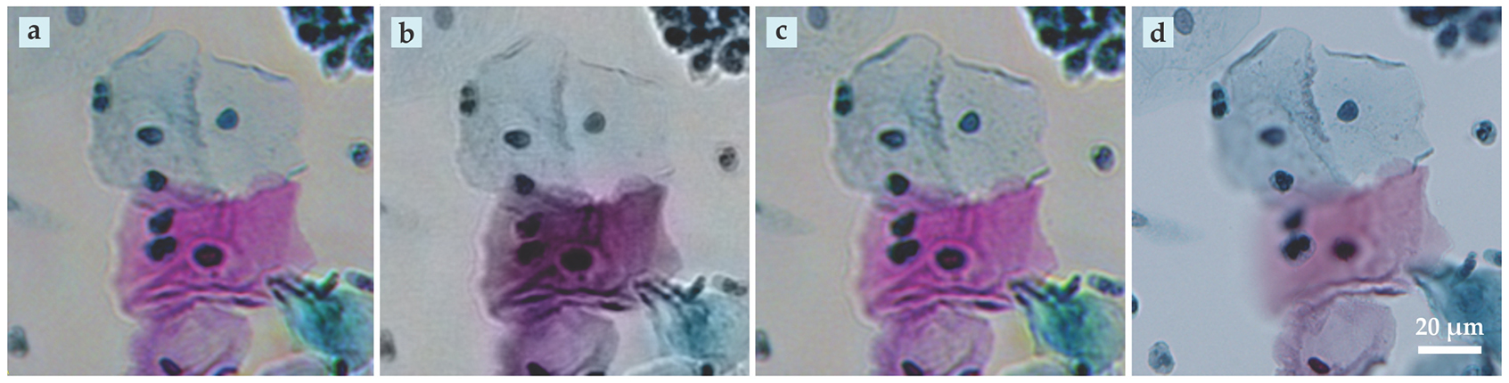
Despite the use of quasi-monochromatic illumination—for example, with a bandwidth of 1–10 nm—and depending on the level of temporal coherence that is desired, color images can still be generated by sequential or simultaneous illumination of the same object at different wavelengths, typically in the red, green, and blue parts of the spectrum. When combining these quasi-monochromatic images into a single color image, twin-image noise—strongly present when phase recovery is not used or fails—and other spatial artifacts can lead to subtle rainbow-like color distortions in images. Those artifacts can be removed through colorization procedures, some of which are summarized in figure
Figure 4.

Lens-free color imaging and resolution. Holographic color images can be acquired in different ways. (a) In demosaiced pixel superresolution, the sample is simultaneously illuminated at different wavelengths and the hologram recorded with a color sensor. (b) Another approach is to work in the so-called YUV color space, which separates the brightness component (Y) from the color or chrominance components (U and V). In YUV averaging, the brightness component is obtained at high resolution and the chrominance components at low resolution. (c) Holograms taken at three different wavelengths in the red, green, and blue parts of the spectrum can be digitally merged to create the color image. All three methods compare favorably in resolution with (d) the image acquired using a conventional microscope. (Adapted from ref.
Sensing
Beyond their application as imaging tools, lens-free on-chip microscopes can also be used in sensing applications. Here the captured images are automatically processed to determine the quantities of objects such as cells, viruses, nanoparticles, and biomolecules. The large space–bandwidth product is again a key feature in such applications because it enables the measurement of large numbers of objects over a wide field of view and a large sample volume.
Unlike fluorescence microscopes, holographic lens-free sensing cannot directly make use of common biochemically selective fluorescent labels due to the incoherent nature of fluorescence. However, lens-free holographic microscopy is fully compatible with scattering-based labels such as metallic nanoparticles with plasmonic resonances, which strongly scat- ter incident light whose frequency resonates with the natural frequency of the electrons in the nanostructure.
As an example, this approach has been used to identify and differentiate two types of immune cells, CD4+ and CD8+ cells, whose relative levels indicate the progression of HIV/AIDS and other diseases. 14 Without labeling, the two types of white blood cells are virtually indistinguishable under an optical microscope. By labeling CD4+ cells with gold nanoparticles coated with antibodies to the CD4 glycoprotein, and by labeling CD8+ cells with silver nanoparticles coated with anti-CD8 antibodies, the two types of cells become distinguishable using lens-free holographic microscopy combined with a machine learning approach.
Lens-free holographic microscopy has also been used in conjunction with selective biochemical labels to sense biological molecules outside of cells. DNA strands with a specific sequence can be detected by capturing them with short DNA chains anchored to a substrate. Different short DNA chains then bind to the other half of the target strands. If those second chains are labeled with microparticles, a lens-free microscope can detect the light scattered by the particles and thereby sense the DNA strands. 15
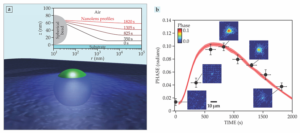
Another label-free sensing application, illustrated in figure
Figure 5.

Self-assembled nanolens-enhanced holographic on-chip microscopy. (a) Nanometer-sized objects are too weakly scattering to be detected by lens-free on-chip microscopy. A liquid nanolens that self-assembles around a nanoparticle makes them detectable. The inset shows the build-up of a nanolens over time as hot vapor condenses on the cold substrate and around the particle. (b) The experimentally measured optical phase signal (black points) from an 83-nm-diameter bead agrees well with theoretical predictions (red band). The insets show experimental images for select points. As the nanolens develops, the signal first grows, but then diminishes when the nanolens becomes too thick. (Panel a adapted from E. McLeod et al., ACS Nano 8, 7340, 2014; inset to panel a and panel b adapted from ref.
The nanolenses can self-assemble around each particle on the substrate through various means. Flow-based formation takes advantage of gravity to flow a centimeter-sized liquid droplet over the objects to be sensed. Nanodroplets left in its wake and pinned to the objects serve as the nanolenses. In solvent evaporation, a dilute polymer solution is deposited on the substrate. Polymer nanolenses are left behind when the solvent evaporates. A third and powerful method is to expose the target nano-objects on a cool substrate to a hot vapor. The nanolenses form via condensation from the vapor. 1 , 10 With the aid of such nanolenses—and automated image processing routines—individual particles as small as 40 nm can be detected over a field of view greater than 30 mm2 and sized to within ±11 nm. 16
Lens-free on-chip microscopy can also be used to detect unlabeled biological molecules by employing a nanostructured plasmonic substrate. The substrate is biochemically designed to capture a specific protein or other target molecule. A shift in the plasmon resonance frequency when target molecules specifically bind to the substrate renders the molecules detectible by a lens-free holographic microscope that is field-portable and cost-effective. 17
Lens-free future
The use and applications of lens-free microscopes continue to grow in both academic and industrial settings. Commercialization efforts are ongoing, with some products already available. As some of those approaches mature, we expect to see significantly increased adoption, first by scientists who routinely use microscopes and then by consumers and commercial developers seeking portable and cost-effective microscopy solutions.

One early set of applications that we foresee is in global health and telemedicine. Already, some researchers have begun to field-test portable microscopes in the detection of malaria, other tropical diseases, and waterborne parasites.
In the near future, we expect significant advances in the computational lens-free microscopy field using machine learning tools, in particular deep-learning based methods, which train artificial neural networks to carry out complex computational tasks. The advances will benefit lens-free microscopy, not only in image annotation for detection of a specific object such as a cell or pathogen type, but also in image reconstruction. In fact, recent phase recovery and twin-image elimination strategies have already benefited from emerging concepts of deep learning in neural networks. With those strategies, it has been possible to reconstruct holograms using one measurement—that is, at a single sample height—which not only improves the overall performance of holographic image recovery but also reduces the number of measurements needed. 18
Further improvements in performance will drive increased adoption of lens-free microscopes. Potential advances include higher resolution, better contrast, and faster imaging speed, and, in the case of sensing applications, greater sensitivity and specificity. Because lens-free microscopy is a computational-imaging approach, resolution is closely associated with the signal-to-noise ratio of the raw holograms. In that sense, lens-free imaging is similar to other modern microscopy modalities such as localization based fluorescence super-resolution imaging. Thus, better image sensors with higher signal-to-noise ratio may lead to improved resolution and contrast.
Imaging speed is a combination of hardware image acquisition time and of computational processing and image reconstruction time. Improvements in those areas will lead to real-time video-rate reconstruction and display of microscopic objects at submicron resolution. Such advances will surely be based on parallel processing and modern graphics processing units.
We also believe that when using self-assembled liquid nanolenses to enhance detection sensitivity, the current size limit of 30–40 nm could be surpassed through optimization of the light source—for example, by using shorter illumination wavelengths—and improved nanolens formation procedures. Finally, biological specificity is primarily a biochemistry problem. We look forward to seeing advanced biochemical techniques combined with lens-free microscopes to enhance performance in various sensing applications.
References
1. A. Ozcan, E. McLeod, Annu. Rev. Biomed. Eng. 18, 77 (2016). https://doi.org/10.1146/annurev-bioeng-092515-010849
2. M. Roy et al., Biosens. Bioelectron. 88, 130 (2017). https://doi.org/10.1016/j.bios.2016.07.115
3. J. Garcia-Sucerquia et al., Appl. Opt. 45, 836 (2006). https://doi.org/10.1364/AO.45.000836
4. O. Mudanyali et al., Lab Chip 10, 1417 (2010); https://doi.org/10.1039/c000453g
D. Tseng et al., Lab Chip 10, 1787 (2010). https://doi.org/10.1039/c003477k5. A. Greenbaum et al., Nat. Methods 9, 889 (2012). https://doi.org/10.1038/nmeth.2114
6. S. Seo et al., Lab Chip 9, 777 (2009). https://doi.org/10.1039/B813943A
7. X. Cui et al., Proc. Natl. Acad. Sci. USA 105, 10670 (2008). https://doi.org/10.1073/pnas.0804612105
8. W. Bishara, S. O. Isikman, A. Ozcan, Ann. Biomed. Eng. 40, 251 (2012). https://doi.org/10.1007/s10439-011-0385-3
9. R. C. Hardie et al., Opt. Eng. 37, 247 (1998). https://doi.org/10.1117/1.601623
10. E. McLeod, A. Ozcan, Rep. Prog. Phys. 79, 076001 (2016). https://doi.org/10.1088/0034-4885/79/7/076001
11. T.-W. Su, L. Xue, A. Ozcan, Proc. Natl. Acad. Sci. USA 109, 16018 (2012). https://doi.org/10.1073/pnas.1212506109
12. J. R. Fienup, Appl. Opt. 21, 2758 (1982). https://doi.org/10.1364/AO.21.002758
13. Y. Wu et al., Sci. Rep. 6, 28601 (2016). https://doi.org/10.1038/srep28601
14. Q. Wei et al., Sci. Rep. 3, 1699 (2013). https://doi.org/10.1038/srep01699
15. F. Colle et al., Lab Chip 13, 4257 (2013). https://doi.org/10.1039/c3lc50707f
16. E. McLeod et al., ACS Nano 9, 3265 (2015). https://doi.org/10.1021/acsnano.5b00388
17. A. E. Cetin et al., Light: Sci. Appl. 3, e122 (2014). https://doi.org/10.1038/lsa.2014.3
18. Y. Rivenson et al., https://arxiv.org/abs/1705.04286 .
More about the authors
Euan McLeod is an assistant professor of optical sciences at the University of Arizona in Tucson, Arizona. Aydogan Ozcan is a Chancellor’s Professor at UCLA and an HHMI Professor at the Howard Hughes Medical Institute.


