Ice fracturing
DOI: 10.1063/PT.3.5270

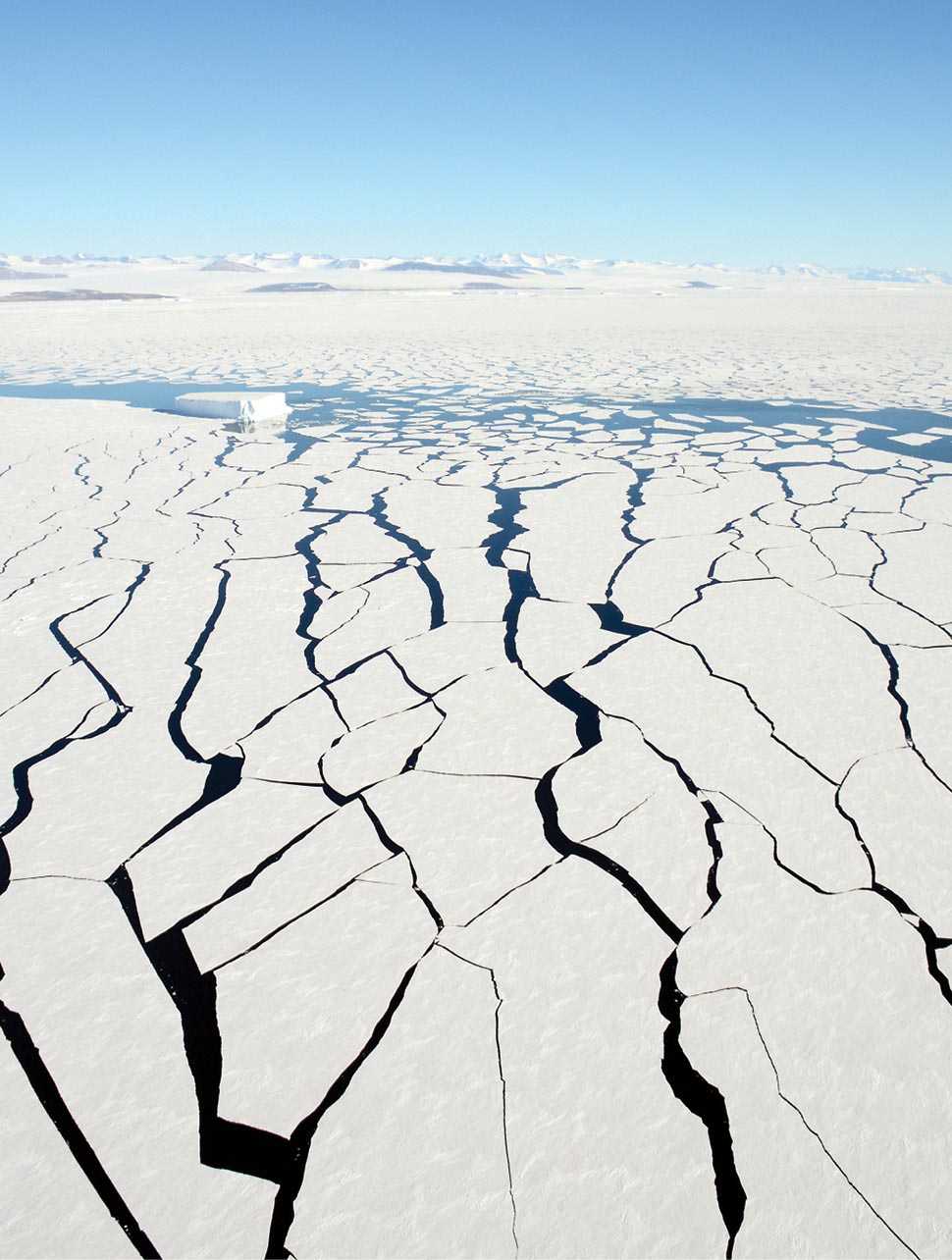
Growing across the floating shelf of Thwaites Glacier in West Antarctica is a giant crack that will eventually become long enough to cause the ice shelf to collapse. That will mean the loss of a buttress against the advance of ice upstream of where the glacier is grounded to bedrock. And as a result, sea level will rise at an increasing rate. Thwaites is not alone. Distributed around some 70% of the continent’s perimeter are many such shelves that perform the same function. They, too, are vulnerable to collapse.
The breakup of ice in the Arctic has similar environmental consequences. Although it is decreasing in extent because of global warming, sea ice covered an area of more than 14 million km2 in March of this year. That’s greater than the area of the continental US and Mexico combined. The ice cover serves as a barrier to the transfer of heat and moisture from the ocean to the atmosphere. But it is riddled with defects. Under the action of wind and ocean current, cracks form and open, accelerating that transfer.

PETER REJCEK/NSF
In those and other instances, the loss of the ice’s structural integrity is rooted in the nucleation, propagation, and interaction of cracks. Exactly how that happens in large masses of ice is an open question and remains a topic of current research. Reviewing the various hypotheses is beyond the scope of this article. My purpose, rather, is to describe the physical mechanisms that govern fracture and, where possible, to elucidate the larger picture.
Scientists have gained insight into those mechanisms largely through experiments in the laboratory, where the main factors at play—temperature, rate of loading, stress, and microstructure—can be controlled and varied in a systematic manner and their effects quantified. The combination of optical transparency and millimeter-scale microstructure in ice allows cracks inside the material to be visible to the unaided eye, which helps in analyzing its fracture mechanics.
This article is limited to the fracture of ice formed from water and loaded under terrestrial conditions. For citations to the original literature and derivations of the functional relationships discussed here, I recommend consulting references and .
Structure of ice
The microstructure of ice, like that of any material, is key to understanding its behavior. Whether in the form of a polar glacier, a floating ice cover, or an ice cube in the refrigerator, ice is made from the aggregation of grains joined at their boundaries. When formed under terrestrial conditions, the grains are typically 1–10 mm in diameter. A grain’s shape may be either equiaxed, in which it has roughly the same length in any direction, or columnar, in which it is longer in one direction than the others, much like a candle, as shown in figure
Figure 1.

Granular ice (left) and columnar ice (right), photographed under polarized light. The granular ice was produced through the consolidation of millimeter-sized grains of ice. The columnar ice was produced through the unidirectional crystallization of fresh water along the vertical direction X3. (Courtesy of Narayana Golding and Daniel Iliescu, Dartmouth College.)
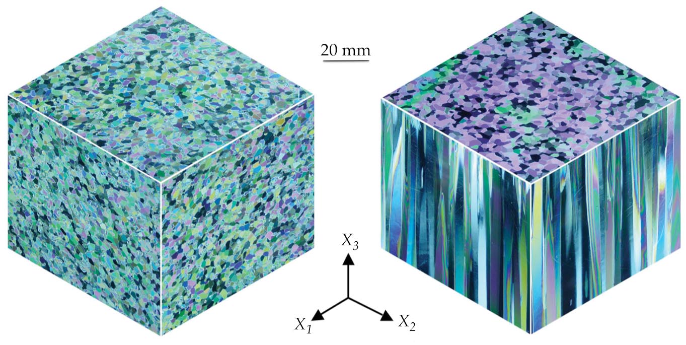
Equiaxed aggregates, termed granular ice, describe glaciers and icebergs and form through the consolidation of snow. Columnar-shaped aggregates, which include a small volume fraction (0.05, typically) of submillimeter-sized pockets of brine, characterize floating sea ice covers and are produced through unidirectional solidification—the vertical transfer of heat along the columns. Regardless of their shape, the grains adopt a crystalline structure in which the H2O molecules are arranged three dimensionally in a periodically repeating array and are held together by hydrogen bonds.
The basic building block, or unit cell, possesses hexagonal symmetry, denoted Ih. Although the orientation of the unit cell remains fixed in any given crystal, in granular ice it varies from grain to grain in an apparently random manner. So even though hexagonal symmetry imparts anisotropic behavior to an individual crystal—making each crystal’s properties dependent on direction—the aggregate as a whole exhibits isotropic behavior.
In columnar ice, on the other hand, the unit cell adopts a preferred orientation. Depending on the conditions of solidification, the long axis of the cell, termed the c-axis, either aligns with the vertical direction, running parallel to the long axis of the grains, or is confined to the horizontal plane, running generally in various directions within that plane. As a result, columnar aggregates possess a preferred orientation and exhibit anisotropic behavior.
Inelastic behavior
Ice does not always break up or fracture when loaded—that is, behave in a brittle manner. When loaded slowly, it deforms in a plastic or ductile manner. Antarctic glaciers, for instance, flow under the force of gravity and can develop strain in excess of unity (100%) without breaking. Similarly, icicles can bend through an angle up to 75° under the force of wind. That kind of behavior originates through the stress-driven slipping of the individual grains on the basal planes of the Ih lattice. The process is analogous to the slipping of cards in a deck. It involves the movement, or “glide,” of line defects, termed crystal dislocations, and begins once the shear stress on the planes reaches a critical level.
Once activated, slip accommodates the strain
The equation dictates how the flow stress increases with rising strain rate, scaling as
Microstructure enters the picture in two ways. First, the plastic parameter
The lower value means that the bending load for plastic flow at a strain rate imposed by the rate of loading is greater than the bending load for aggregates in which the c-axes are oriented in the horizontal plane. Given that the resistance to crack propagation is relatively insensitive to c-axis orientation, the effect of the vertical orientation is to reduce the strain rate that marks the transition from ductile to brittle behavior.
The second way microstructure appears is through grain size. For reasons described below, the load required to propagate cracks decreases as the grain size increases and is lower under tension than under compression. Thus, because of the influence of microstructure and stress, the strain rate that marks the DB transition, expressed as
Brittle failure
When activated by the appropriate combination of factors, brittle failure is marked by a sudden loss of load-bearing ability. At play is crack mechanics, particularly its propagation. Cracks weaken a material by concentrating stress in proportion to the square root of their lengths. The effect of those cracks on strength is expressed in terms of a crack-tip stress intensity factor
Because of their thermomechanical history, natural icy bodies generally contain cracks whose lengths can reach more than a meter, whereas pristine ice—the kind most often studied in the laboratory—develops cracks whose lengths are set by the grain size of each aggregate. For both natural and pristine ice, the brittle-failure stress
The parameter
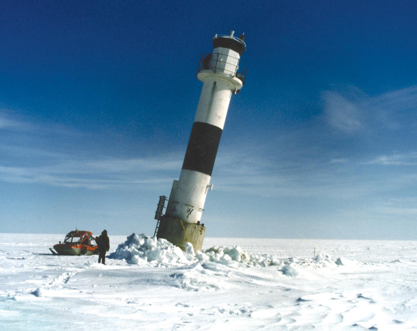
Compared with other natural materials, ice offers little resistance to propagating cracks. The combination of low toughness and crack length generally greater than 1 mm dictates that pristine ice undergo brittle failure at quite low stress—on the order of about 1 MPa under tension and 10 MPa under compression. Defective natural ice is even weaker because it has larger cracks. Even so, when a large mass, such as a sheet of sea ice, under the action of wind pushes against an offshore structure, such as the lighthouse shown in figure
Figure 2.

This lighthouse in the Baltic Sea was photographed after it interacted with the wind-driven ice cover. (Adapted from ref.
To appreciate why ice fails at a higher stress when loaded under compression than under tension, consider the underlying mechanisms. In pristine material, cracks must first nucleate. That happens as stress builds up locally within the body, either by dislocations impinging on grain boundaries and piling up there or by grains sliding along their boundaries. Once the grain-boundary stress is high enough, it is relieved by the creation of grain-sized microcracks, inclined at around 45° to the direction of loading. Tension acts to open those microcracks and is usually great enough when combined with a long enough crack to generate a sufficiently large stress intensity factor and cause unstable crack propagation. And that unstable propagation may happen either when the crack first nucleates or shortly thereafter, when it creates a fracture plane perpendicular to the direction of loading.
Compression, on the other hand, closes cracks, which leads to a more complicated failure process. Because of their inclination, the upper crack faces tend to slide over the lower faces as long as the shear stress on the plane of the crack is sufficient to overcome friction. At the crack tips, sliding generates tension, which is relieved through the initiation of short, out-of-plane extensile or secondary cracks, known as wing cracks, that tend to align along the direction of loading. 5 , 6
When those wing cracks are produced, tension is transferred to their tips, thereby accounting for how a compressive load can generate an internal tensile stress. As the load increases, sliding continues: The mouths of the wing cracks open, the tensile stress at their tips increases, and the wings begin to lengthen in a stable manner once the crack-tip stress intensity factor reaches the critical level. The wing cracks interact with other wings, the ensemble of which eventually forms a macroscopic fault that runs parallel to the direction of loading. At that point, terminal failure ensues, and the ice loses its load-bearing ability. Frictional sliding, in other words, is the reason why compressive strength is greater than tensile strength.
Natural icy bodies are seldom loaded simply by pushing or pulling in one direction. More commonly, the ice is loaded three dimensionally—for example, by bending about two axes or through confinement, as in a pressure cell or beneath an indenter. Multiaxial loading has little effect on the tensile stress required to cause a primary crack to propagate, and so it has little effect on tensile strength. On compressive failure, however, the effect is large. That’s evident from the fact that a confining pressure as small as 10% of the applied compressive stress almost doubles the strength. The reason is twofold: Confinement acts to close wing cracks and therefore reduces the stress intensity at their tips. It also raises the applied stress acting normal to the plane of the primary crack. And through friction, that component of stress increases the resistance to sliding.
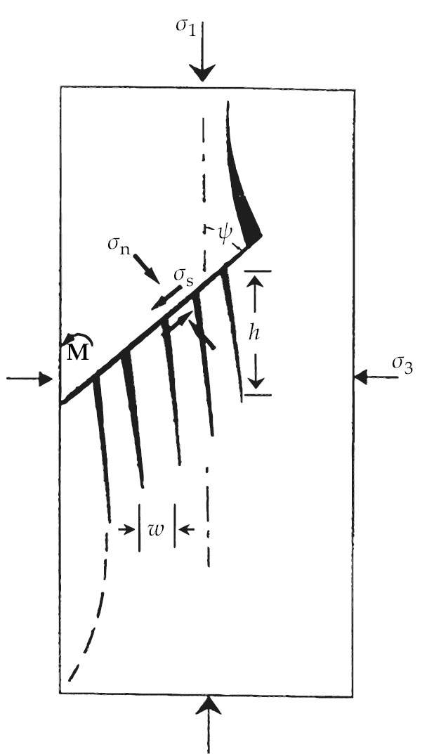
The frictional model just described implies that sliding occurs uniformly across the opposing faces of the parent cracks. Confinement, however, induces nonuniform sliding. That has the effect of generating on one side of the parent crack (and sometimes on alternating sides) localized zones of tensile stress. The tension is again relieved by cracking, in this case by the initiation of sets of other wing cracks. Each set creates, in effect, microcolumns that are fixed on one end and free on the other. Frictional drag across their free ends bends and then breaks the microcolumns under an applied compressive load lower than that required to buckle the columns.
The mechanism acts like the sliding of a thumb across the teeth of a comb—hence the term comb–crack mechanism, pictured schematically in figure
Figure 3.

Comb cracks, in a schematic. Fundamental to the brittle failure of ice loaded under multiaxial compressive stresses
Satellite imagery has revealed intersecting sets of strike–slip-like faults, termed linear kinematic features, 7–9 that run hundreds of kilometers through the winter sea-ice cover on the Arctic Ocean. Those features were activated intermittently through wind-induced compressive stresses on the order of kilopascals. And they closely resemble intersecting coulombic shear faults generated in the laboratory from winter sea ice under megapascal compressive stresses (see reference , chapter 15).
The three orders of magnitude difference in stress reflects a six orders of magnitude difference in the length of sliding, primary cracks—kilometer versus millimeter—and the square-root dependence of the stress intensity factor on crack length. The coefficient of friction of ice on ice is independent of scale and would account for the similarity in angle of intersection on both large and small scales.
In 2001 Carl Renshaw and I developed a model based on the comb–crack mechanism. 10 It incorporates only physically measurable parameters—fracture toughness, crack size, the coefficient of kinetic friction, and the ratio of the confining stress to the major stress. It captures the effect of confinement on the brittle compressive strength of ice. And in using no adjustable parameters, the model also accounts for the strength of various rocks and minerals.
Plastic versus coulombic faulting
So far in this article, crack mechanics has accounted for the sudden loss of load-bearing ability by ice on rapid loading. That is not always the case, however. Under compression, the hydrostatic component of the stress tensor becomes large enough to suppress frictional sliding, and it thereby shuts down the comb–crack mechanism and prevents failure via coulombic faulting.
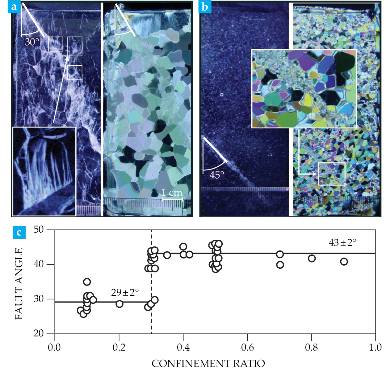
Yet the ice continues to deform. The shear component of the stress tensor reactivates dislocation glide—the movement of the dislocations across crystallographic planes—accompanied at high strain rates by adiabatic heating. That dislocation glide eventually leads to failure through the development of a different kind of fault known as a plastic fault. The transition from coulombic faulting to plastic faulting occurs when the degree of confinement, defined as the ratio of the least compressive stress to the most, reaches a critical level
Plastic deformation generates heat. Indeed, about 80% of plastic work is expended as heat. Although ice is a poor thermal conductor, at low strain rates the heat generated through dislocation glide is dissipated over time on selective planes of the Ih crystals. At high strain rates, on the other hand, there’s not enough time for the heat to dissipate. As a result, the slipping zones simply heat up and become weaker. (Recall that the parameter
The result is a band composed of soft, tiny grains, oriented at around 45° to the direction of shortening. What’s thus formed on a plane of maximum shear stress is a plastic fault (see, for example, reference ). Figure
Figure 4.

Shear faults and plastic faults under confinement. (a) This thin (1 mm) section of a coulombic shear fault was formed in freshwater ice compressed at −10 °C under little (
In practice, objects can experience a lot of compression when one dents another, as would happen, for instance, when an iceberg and a ship collide. Indentation experiments on both large and small bodies revealed that ice can fail at strengths as high as 50 MPa. The near-surface, highly confined regions are essentially crack-free and composed of recrystallized grains, 12 , 13 indicative of failure via plastic faulting.
Like coulombic faulting, plastic faulting is not limited to ice. Evidence exists that Earth minerals antigorite, granite, and olivine fail by the same mechanism when rapidly loaded under a high degree of triaxial confinement. 14
Returning to the Antarctic ice shelf that I began this article with, crack growth is a slow process, at least up to the point of collapse. Although several mechanisms are at play, including surface flooding and hydrofracturing, the growth might be triggered by ocean swells.
15
,
16
If so, then cyclic variations in the stress intensity factor
Perhaps crack growth and its time of collapse could be modeled according to the Paris–Erdogan law, 17 which states that the increase in crack length per loading cycle scales with the change in the stress intensity factor—that is, with the product of the change in tensile stress and the square root of crack length. But so far as I’m aware, no analysis of that kind has yet been made.
I thank colleagues Harold Frost and Carl Renshaw for fruitful discussions over the years and my students, who performed the research on which some of this article is based. I am grateful for financial support from NSF.
References
1. E. M. Schulson, P. Duval, Creep and Fracture of Ice, Cambridge U. Press (2009).
2. E. M. Schulson, C. E. Renshaw, Annu. Rev. Earth Planet. Sci. 50, 323 (2022). https://doi.org/10.1146/annurev-earth-032320-085507
3. K. L. Litwin et al., J. Geophys. Res. 117, n/a (2012). https://doi.org/10.1029/2012JE004101
4. American Petroleum Institute, Recommended Practice for Planning, Designing and Constructing Structures and Pipelines for Arctic Conditions, 2nd ed. (1995).
5. W. F. Brace, E. G. Bombolakis, J. Geophys. Res. 68, 3709 (1963). https://doi.org/10.1029/JZ068i012p03709
6. M. F. Ashby, S. D. Hallam, Acta Metall. 34, 497 (1986). https://doi.org/10.1016/0001-6160(86)90086-6
7. J. R. Marko, R. E. Thomson, J. Geophys. Res. 82, 979 (1977). https://doi.org/10.1029/JC082i006p00979
8. R. Kwok, in IUTAM Symposium on Scaling Laws in Ice Mechanics and Ice Dynamics, J. P. Dempsey, H. H. Shen, eds., Springer (2001), p. 315.
9. R. Kwok, M. D. Coon, J. Geophys. Res. 111, C11S21 (2006). https://doi.org/10.1029/2006JC003877
10. C. E. Renshaw, E. M. Schulson, Nature 412, 897 (2001). https://doi.org/10.1038/35091045
11. N. Golding, E. M. Schulson, C. E. Renshaw, Acta Mater. 60, 3616 (2012). https://doi.org/10.1016/j.actamat.2012.02.051
12. R. Frederking, I. J. Jordaan, J. S. McCallum, in IAHR 90: Proceedings of the 10th International Symposium on Ice, Volume 2, Helsinki University of Technology (1990), p. 931.
13. J. Wells et al., Cold Reg. Sci. Technol. 65, 314 (2011). https://doi.org/10.1016/j.coldregions.2010.11.002
14. C. E. Renshaw, E. M. Schulson, J. Geophys. Res. Solid Earth 122, 1088 (2017). https://doi.org/10.1002/2016JB013407
15. R. A. Massom et al., Nature 558, 383 (2018). https://doi.org/10.1038/s41586-018-0212-1
16. M. H. Meylan et al., Proc. R. Soc. A 477, 20210173 (2021). https://doi.org/10.1098/rspa.2021.0173
17. P. Paris, F. Erdogan, J. Basic Eng. 85, 528 (1963). https://doi.org/10.1115/1.3656900
18. A. Engelbrektson, Evaluation of Extreme Ice Forces on a Lighthouse in the Bothnian Bay: A Study of the Björnklack Event in April 1985, Ice Forces Against Offshore Structures rep. no. 1, National Administration of Shipping and Navigation and University of Luleå, Sweden (1987).
More about the authors
Erland Schulson is director of the Ice Research Laboratory and the George Austin Colligan Distinguished Professor of Engineering at Dartmouth College in Hanover, New Hampshire.


