Gently balance a coin edge-down on a flat surface and give it a sharp flick on the side to set it spinning. You’ll observe that the coin’s initial pure rotation turns into a mix of spinning and rolling before dissipative forces bring the coin to a stop. That behavior, like almost all other classical dynamics phenomena, was explained in the 18th and 19th centuries, beginning with the work of Leonhard Euler (1707–83). You might expect that repeating the disk game with a ring would yield essentially the same results. But to the best of our knowledge, until recently the ring game was not carefully observed and rolling-ring dynamics was not carefully studied.
Aggravation turns to joy
On a chilly afternoon, one of us (Jalali) was deeply frustrated by a science problem that seemed to defy any reasonable approach. To cope, he took off his wedding ring, spun it on his glass-covered desk, and began to apathetically watch the motion. What he observed was quite different from what he knew to expect for a rolling disk or coin. Figures 1a and 1b show the translational motion along the table for a coin and a ring. Initially, both objects have the same sense for their orbital and spin motions—that is, both are counterclockwise, viewed from above. But whereas the coin always has the same orbital and spin sense, the ring’s translational motion flattens out after a while, and eventually the ring orbits in the sense opposite to that of its spin.
Figure 1. High-speed images of (a) a rolling, spinning disk and (b) a rolling, spinning ring show the differences in their trajectories. The disk’s wobbly orbit is always in the same sense as its counterclockwise rotation. The ring begins its motion similarly, but in time the ring’s translational motion straightens out, then the orbit reverses. (c) The illustrations here define the parameters and coordinates used in modeling disk and ring trajectories. The unit vector e1 is always parallel to the horizontal plane, and e2 is normal to the circular edge of the ring. The coordinate of point A with respect to the contact point is rA=rG+(h/2)e2.
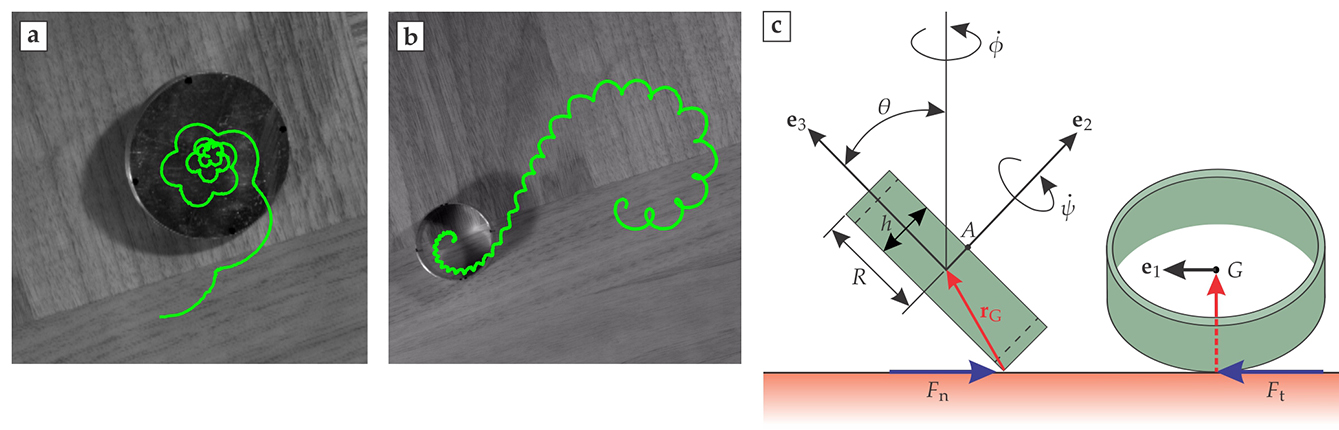
A few weeks later, the two of us met socially for dinner and spent much of the evening spinning our wedding rings and marveling at their incredible behavior. Our joy of discovery led to weeks of theoretical modeling and investigations with a high-speed camera. We learned that the ring’s secret lies in how it responds to the force of air drag.
Setting up the problem
In our analysis, we consider a ring of mass , moment of inertia tensor , radius , and width . Our goal is to describe the kinematics of motion by specifying the orientation of the body and the position of its center of mass. To describe the orientation, we use the Euler angles , , and and a moving coordinate system with unit vectors , , and . Those coordinates and unit vectors and some of the ring parameters are illustrated in figure 1c, which also indicates the two horizontal components of friction: supports the ring’s spin about its symmetry axis, and keeps the ring in its curved path.
With so many parameters and coordinates, the analysis gets involved. But the mathematical and physics technology is the sort of thing you’d find in a mechanics textbook.
Let be the sum of the normal and frictional forces at the contact point and be the downward-directed force of gravity. According to Newton’s second law of motion, the total force accelerates the center of mass, and the torque changes the angular momentum . Here is the angular velocity, and we sum over repeated indices. The angular velocity is readily related to changes in the Euler angles via , where the overdot denotes time differentiation.
We assume that the ring rolls without slipping. Eliminating the contact force between the equations of motion for the acceleration of the center of mass and for the change in angular momentum leads to a single equation of motion. It’s a complicated equation, and not one whose structure we need to analyze in detail. Indeed, we will reveal its implications by means of simulated solutions. Nonetheless, we present it for completeness (you can find additional details in our paper cited in the additional resources).
Here, is the velocity of center of mass in the laboratory frame, and . It is almost impossible to track the motion of the center of mass experimentally because it lies in the hollow central space of the ring. We therefore use the point along the axis of the ring that lies in the plane of the top edge, marked by in figure 1c. Point can be identified with the help of image processing methods and tracked both in experiments and simulations.
Drag and drop
Depending on the initial value of , a ring governed by the above equation of motion can move in a periodic or quasiperiodic orbit. Figure 2a shows a representative simulation of an O-shaped, quasiperiodic orbit. The ring trajectories always orbit in the same sense as the ring rotates; we never find S-shaped trajectories similar to those executed by rings in the real world.
Figure 2. Representative tabletop trajectories of a ring proportioned like a wide wedding band. Distances are in units of the ring’s radius. Variable line colors indicate the value of θ in degrees. The curves show the projection onto the tabletop of the ring’s point A. (Point A and θ are defined in figure 1c.) (a) Absent drag forces, the ring executes a periodic orbit or, as shown here, a quasiperiodic orbit composed of precessing cycloids. (b) Drag forces can profoundly affect the trajectories. As discussed in the text, such forces can be described in terms of three drag coefficients Ci. The green curve (with no θ information) corresponds to (C1,C2,C3)=(0.17,0.053,0.17). The red and blue curve corresponds to (C1,C2,C3)=(0.02,0.053,0.08); it exhibits a change in its orbital sense—a consequence of the relatively low values of C1 and C3.
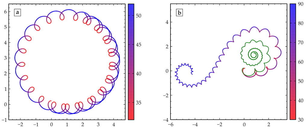
Evidently, we missed something significant in the simple model presented above. So we systematically examined the unmodeled effects of intermittent slippages, elastic vibrations of the ring, and air drag. Given the experimentally observed trajectories, we quickly ruled out slippage and vibrations. The game changer is air drag.
The effect of that drag on is typically described in terms of dimensionless rotational drag coefficients. For a general three-dimensional object, every component of the angular velocity corresponds to a different drag coefficient that needs to be found experimentally. A simple and useful approximation often invoked in studies of turbulent flow is that air drag corrects each determined by the equations of motion with an additive term: (no index sum).
The surface characteristics of an object rotating on a table affect and more than because rotations about and tend to compress air between the object and the table. Since the air can escape from the central hole of a ring, one would intuitively expect and to be smaller for a ring than a disk of the same radius. Figure 2b shows how two ring trajectories with the same initial conditions differ as drag coefficients vary. For the parameters relevant to the hollow geometry of a ring, the simulated trajectory includes a prominent retrograde turn, very much like that observed experimentally.
To gain further insight into the physics behind the ring’s reverse turn, we studied the behavior of , the friction component that curves the ring trajectory, at those points on the orbit where is a local maximum. After a few orbital cycles, we found, drag forces are large enough that is small; the ring walks along an almost straight line. Subsequent interplay between the drag and other forces brings back to life, but now the frictional force is reversed compared with its initial direction. Thus, the ring’s center of mass orbits in the sense opposite to that of the ring’s spin.
References
1. L. A. Pars, A Treatise on Analytical Dynamics, Wiley, 1965).
Mir Abbas Jalali is a visiting scholar in the department of astronomy at the University of California, Berkeley, and a professor of mechanical engineering at Sharif University of Technology in Tehran, Iran. Mohammad-Reza Alam is an assistant professor of mechanical engineering at UC Berkeley.
A subtle macroscopic effect in the space between two birefringent plates produces a measurable Casimir torque.
June 01, 2025 12:00 AM
Get PT in your inbox
Physics Today - The Week in Physics
The Week in Physics" is likely a reference to the regular updates or summaries of new physics research, such as those found in publications like Physics Today from AIP Publishing or on news aggregators like Phys.org.